Category: Manuals

sears kenmore 158 sewing machine manual

Kenmore’s 158 series sewing machines, like the 158.90 and 158.1980x, are popular models with readily available manuals for users seeking guidance and support.

These manuals, often found online, provide detailed instructions for operation, maintenance, and troubleshooting, ensuring a positive sewing experience.

Overview of the Kenmore 158 Series

The Kenmore 158 series represents a line of dependable sewing machines manufactured by Sears, known for their robust construction and user-friendly design. These machines, including models like the 158.90 and variations such as the 158.1980x, gained popularity for both basic and intermediate sewing tasks.

Numerous manuals are accessible online, detailing the features and operation of these machines. They cater to a wide range of sewing needs, from simple alterations to more complex projects. The availability of these resources contributes to the enduring appeal of the Kenmore 158 series among sewing enthusiasts and beginners alike, offering accessible support.

Why This Manual is Important

A Kenmore 158 sewing machine manual is crucial for maximizing the machine’s potential and ensuring its longevity. These manuals provide step-by-step instructions for threading, bobbin winding, stitch selection, and maintenance procedures, preventing damage and ensuring optimal performance.

Access to a manual empowers users to troubleshoot common issues independently, saving time and repair costs. Whether a digital download or a physical copy, the manual unlocks the full functionality of the machine, allowing both novice and experienced sewers to confidently tackle a variety of projects. It’s an invaluable resource!

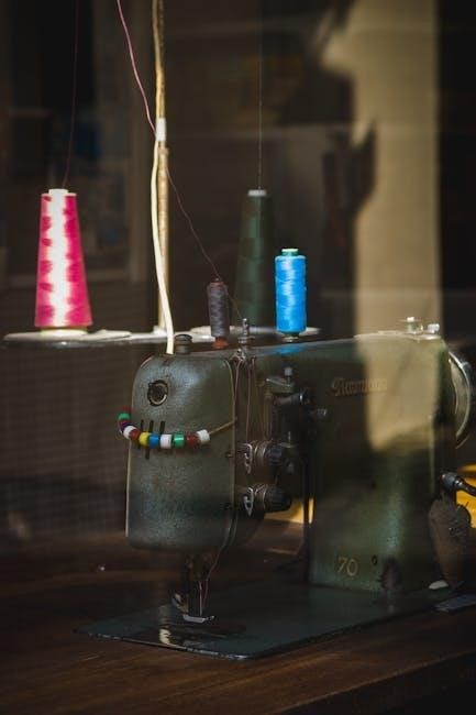
Machine Features and Components

Kenmore 158 machines boast key parts like a bobbin winding system, stitch selection dial, and tension control, detailed within the comprehensive sewing machine manual.

Identifying Key Parts

The Kenmore 158 sewing machine manual meticulously details each component. Users will find illustrations and descriptions of the handwheel, presser foot, needle clamp, and feed dogs.

Crucially, the manual highlights the bobbin case and cover, essential for understanding the threading process. It also identifies the stitch length dial, stitch width dial, and reverse lever, allowing for precise stitch control.

Furthermore, the manual points out the power switch, foot controller, and tension dials, ensuring users can safely and effectively operate their machine. Proper identification of these parts is vital for maintenance and repair.

Bobbin Winding System

The Kenmore 158 manual provides a step-by-step guide to winding the bobbin. Initially, it instructs users to place the thread spool on the spool pin and guide the thread through the tension disc.

Next, the manual details how to thread the bobbin and engage the bobbin winding mechanism, typically by pushing the bobbin spindle to the right. It emphasizes the importance of consistent thread tension during winding.

Finally, the manual explains how to disengage the winding mechanism and remove the full bobbin. Correct bobbin winding is crucial for achieving even stitches and preventing machine malfunctions.

Thread Tension Control

The Kenmore 158 sewing machine manual highlights the importance of proper thread tension for optimal stitch quality. It explains that the tension dial controls the force applied to the upper thread.

Adjusting this dial impacts the balance between the upper and lower threads, influencing the appearance of the stitch on the fabric. The manual advises testing tension on a scrap fabric piece.

Too much tension can cause puckering, while too little results in loose stitches. Finding the correct setting ensures a balanced, professional-looking seam, crucial for various sewing projects.

Stitch Selection Dial

The Kenmore 158 sewing machine manual details the function of the stitch selection dial, a key component for versatility. This dial allows users to choose from a range of stitch patterns, catering to diverse sewing needs.

Options typically include straight stitch, zigzag stitch, and potentially decorative stitches, depending on the specific model. The manual provides clear diagrams illustrating each stitch pattern.

Proper selection is crucial for achieving the desired aesthetic and functionality in projects, from basic seams to intricate embellishments. Understanding the dial’s markings is essential for effective operation.

Setting Up Your Machine

The Kenmore 158 manual guides users through initial setup, covering powering on, essential checks, and proper threading techniques for optimal performance.

Powering On and Initial Checks

Before beginning any sewing project with your Kenmore 158, consult the manual for specific power requirements and ensure the machine is correctly plugged into a grounded outlet.

Upon powering on, verify the power switch functions as expected and that the internal light illuminates, indicating proper electrical connection.

The manual emphasizes checking the handwheel’s free movement; it should rotate smoothly without resistance. Also, confirm the bobbin cover is securely in place and the presser foot is down before attempting to sew, as these are crucial safety and operational prerequisites.

Finally, a quick visual inspection for any loose parts or damage is recommended before each use.

Threading the Machine

The Kenmore 158 manual provides detailed diagrams illustrating the correct threading path, crucial for proper stitch formation. Begin by raising the presser foot and the needle to its highest position.

Follow the numbered guide, typically starting with the spool pin, then through the thread guides, tension discs, and finally, the needle clamp.

Ensure the thread is securely seated in each guide and tension component to prevent skipped stitches or uneven tension. The manual stresses the importance of threading with the presser foot up during initial threading.

Always refer to the specific diagram for your model variation, as slight differences may exist.

Winding and Inserting the Bobbin

The Kenmore 158 manual details a bobbin winding system, typically involving placing the spool on the pin and guiding the thread through tension discs before winding onto the bobbin.

Engage the bobbin winding mechanism, often by pushing the bobbin spindle to the right, and start the machine. Once full, the machine should automatically stop.

To insert the bobbin, open the bobbin case cover and place the bobbin in the designated compartment, ensuring the thread unwinds in the correct direction, as illustrated in the manual.

Draw up the bobbin thread through the tension spring before beginning to sew.

Basic Sewing Techniques

The Kenmore 158 manual guides users through fundamental techniques like straight and zigzag stitching, offering stitch length and width adjustments for varied projects.

Straight Stitching

Mastering the straight stitch is foundational for any sewing project, and the Kenmore 158 manual provides clear instructions. Begin by selecting the straight stitch option on the stitch selection dial.

Ensure the fabric is positioned correctly under the presser foot, aligning the desired seam allowance with the guide markings on the needle plate.

Gently depress the foot pedal to initiate sewing, maintaining a consistent speed for a uniform stitch. The manual emphasizes the importance of guiding the fabric, not pulling it, to prevent distortion.

Practice on scrap fabric to achieve consistent stitch length and straight lines before tackling your final project. Adjust stitch length as needed for different fabric weights and applications.

Zigzag Stitching

The Kenmore 158’s zigzag stitch offers versatility for various applications, from finishing raw edges to creating decorative designs. Select the zigzag stitch on the dial, and adjust the stitch width using the corresponding control.

Wider stitches are ideal for preventing fabric fraying, while narrower stitches are suitable for reinforcing seams. The manual details how to adjust stitch length in conjunction with width for optimal results.

Practice on scrap fabric to understand the effect of different width and length combinations.

Zigzag stitching is also useful for sewing stretch fabrics, allowing the seam to expand and contract with the material. Refer to the manual for recommended settings.

Adjusting Stitch Length and Width

The Kenmore 158 allows precise control over stitch length and width, crucial for achieving desired sewing results. Stitch length is typically adjusted using a dial or slider, influencing the density of stitches per inch.

Shorter stitch lengths are best for delicate fabrics and curves, while longer lengths suit heavier materials and straight seams. Width adjustments, also via a dial, control the side-to-side deviation of the needle.

The manual provides guidance on appropriate settings for different fabrics and stitch types. Experimenting with these controls on scrap fabric is recommended.

Advanced Sewing Techniques

The Kenmore 158 manual details techniques like buttonholes, zipper insertion, and darning, expanding your sewing skills beyond basic straight and zigzag stitches.

Buttonhole Sewing

The Kenmore 158 sewing machine manual provides a dedicated section on creating buttonholes, a crucial skill for garment construction. It outlines the necessary buttonhole foot attachment and explains how to select the appropriate buttonhole settings on the stitch dial.

Detailed diagrams illustrate the process, emphasizing the importance of accurately measuring button size and testing the stitch on scrap fabric. The manual guides users through creating both standard and stretch buttonholes, ensuring a professional finish.

It also offers troubleshooting tips for common issues like uneven buttonholes or thread breakage, empowering users to achieve consistently high-quality results.

Zipper Insertion

The Kenmore 158 sewing machine manual dedicates specific instructions to zipper insertion, covering various techniques for different zipper types. It details the use of the zipper foot, explaining how it facilitates close stitching along the zipper teeth.

The manual illustrates methods for inserting both standard and invisible zippers, providing step-by-step guidance with clear diagrams. It emphasizes the importance of accurate pinning and consistent seam allowances for a professional finish.

Troubleshooting tips address common challenges like puckering or uneven stitching, helping users achieve smooth and secure zipper applications.

Darning and Freehand Embroidery

The Kenmore 158 manual showcases the machine’s versatility beyond basic sewing, including darning and freehand embroidery capabilities. It explains how to disengage the feed dogs, allowing for unrestricted fabric movement essential for these techniques.

Instructions detail using various embroidery stitches and creating decorative patterns. The manual suggests appropriate thread weights and needle types for optimal results.

Darning guidance covers repairing holes and worn areas in fabric, offering techniques for both woven and knitted materials. Users can explore creative embellishments with the machine’s stitch options.

Maintenance and Troubleshooting

The Kenmore 158 manual emphasizes regular cleaning and oiling to maintain peak performance. It also provides solutions for common issues, ensuring longevity.

Cleaning the Machine

Regular cleaning is crucial for the Kenmore 158 sewing machine’s optimal function, as detailed in the manual. Always disconnect the power before beginning any cleaning procedure for safety. Use a soft brush to remove lint and dust from the bobbin area, feed dogs, and around the needle plate.

The manual recommends wiping down the exterior with a slightly damp cloth. Avoid harsh chemicals or abrasive cleaners, as these can damage the machine’s finish. Pay close attention to areas where oil accumulates, as dust can stick to it. A thorough cleaning schedule, as outlined in the manual, will prevent build-up and ensure smooth operation for years to come.

Oiling and Lubrication

Proper lubrication, as described in the Kenmore 158 manual, is vital for maintaining smooth operation and preventing wear. The manual specifies designated oiling points – typically around the bobbin area, gears, and moving parts. Use only sewing machine oil; other lubricants can cause damage.

Apply oil sparingly, using a dropper or oiler, and wipe away any excess. Over-oiling can attract dust and create a sticky residue. The manual details the frequency of oiling, generally recommended after every few uses or when noticing increased friction. Consistent lubrication, following the manual’s guidance, extends the machine’s lifespan.

Common Problems and Solutions

The Kenmore 158 manual addresses frequent issues like thread breakage, skipped stitches, and bobbin problems. Thread breakage often stems from incorrect threading or tension. Skipped stitches can indicate a dull or incorrectly inserted needle. Bobbin issues frequently relate to improper winding or insertion.

The manual provides step-by-step troubleshooting for each, emphasizing re-threading, tension adjustments, and needle checks. Always unplug the machine before attempting repairs. If problems persist, consult the manual’s diagrams or seek assistance from online forums dedicated to Kenmore sewing machines.

Understanding Stitch Patterns

The Kenmore 158 manual details various stitch options, including decorative and stretch stitches, alongside overlock functionality for professional seam finishing.

Users can explore diverse patterns for creative projects and garment construction.

Decorative Stitch Options

The Kenmore 158 sewing machine manual showcases a range of decorative stitch patterns, allowing for personalized embellishments on various projects. These stitches extend beyond basic sewing, offering creative avenues for quilting, appliqué, and garment detailing.

The manual provides clear illustrations and explanations for each stitch, guiding users on appropriate fabric choices and tension settings. From simple floral designs to intricate geometric patterns, the 158 empowers users to add unique touches to their creations. Experimentation is encouraged, fostering individual style and artistic expression through the diverse stitch selection. Proper stitch selection enhances project aesthetics.

Stretch Stitch Applications

The Kenmore 158 sewing machine manual details the utility of stretch stitches for working with knit and other elastic fabrics. These specialized stitches prevent puckering and maintain seam integrity when garments are stretched or worn. The manual illustrates how to select the correct stretch stitch for different fabric weights and project types.

Applications include sewing activewear, lingerie, and everyday clothing where flexibility is crucial. Proper stitch selection and tension adjustments, as outlined in the manual, ensure comfortable and durable seams. Mastering stretch stitches expands the machine’s versatility and sewing capabilities.

Overlock Stitch Functionality

The Sears Kenmore 158 sewing machine manual explains that while not a dedicated overlock machine, the 158 series can simulate overlock stitches using a zigzag setting. This provides a finished edge to fabrics, preventing fraying, and is particularly useful for lightweight materials. The manual details adjusting stitch width and length to achieve an effective overlock-like finish.

This technique is ideal for quick projects or when a full overlock machine isn’t available. It’s important to note that the simulated overlock won’t be as robust as a true overlock seam, but it offers a practical solution for basic edge finishing.

Safety Precautions

The Kenmore 158 manual emphasizes general and electrical safety, alongside careful needle handling to prevent injuries during operation and maintenance procedures.

General Safety Guidelines

Always disconnect the power supply before performing any maintenance, such as changing the needle, cleaning, or oiling the machine, as detailed in the Kenmore 158 manual.

Never operate the sewing machine with a damaged cord or plug, and avoid using extension cords if possible; if necessary, ensure it’s appropriately rated.

Keep fingers away from moving parts, like the needle and presser foot, while the machine is running. Supervise children closely when the machine is in use or stored.

Do not force the fabric under the needle; let the machine feed the material naturally. Always use the correct needle type for the fabric being sewn, as recommended in the manual.

Electrical Safety

The Kenmore 158 sewing machine operates on standard household electrical power; therefore, ensure the voltage matches the machine’s requirements, as specified in the manual.

Never operate the machine in a damp or wet location to prevent electric shock. Avoid using it outdoors or near water sources. Regularly inspect the power cord for damage.

If the machine exhibits any electrical issues – sparking, unusual smells, or overheating – immediately disconnect it from the power outlet and consult a qualified technician.

Do not attempt to repair electrical components yourself; this could be dangerous. Always unplug the machine before cleaning or changing parts, following manual instructions.

Needle Safety

Always disconnect the power supply before changing or working near the needle on your Kenmore 158 sewing machine. Needles are sharp and can cause injury if handled carelessly.

Use only the correct type and size of needle recommended for your fabric in the manual; A mismatched needle can break, potentially causing harm or damaging the machine.

Insert the needle firmly into the needle clamp, ensuring it’s securely fastened. Discard broken or bent needles immediately and safely – do not reuse them.

Never sew over pins or thick materials that could bend or break the needle. Keep fingers clear of the needle area during operation to prevent accidental punctures.

Resources and Support

Numerous online forums and communities offer support for Kenmore 158 owners, alongside readily available manuals and Kenmore’s customer support channels.

Finding replacement parts is often possible through online retailers specializing in vintage sewing machine components.

Finding Replacement Parts

Locating replacement parts for your Kenmore 158 sewing machine can be achieved through several avenues, particularly online. Many websites specialize in vintage sewing machine parts, offering belts, bobbins, needles, and even more complex components.

eBay and other auction sites frequently list parts salvaged from older machines, providing potentially cost-effective solutions. When searching, be precise with the model number (e.g., 158.90, 158.1980x) to ensure compatibility.

Additionally, sewing machine repair shops often stock common parts or can source them for you. Consulting online forums dedicated to Kenmore sewing machines can also yield valuable leads and part numbers.

Online Forums and Communities

Numerous online forums and communities cater specifically to vintage sewing machine enthusiasts, including dedicated spaces for Kenmore models like the 158 series. These platforms offer a wealth of knowledge, from troubleshooting advice to locating hard-to-find manuals and parts.

Members frequently share their experiences, repair tips, and even digitized versions of original Kenmore manuals. Engaging with these communities can provide personalized support and solutions to specific issues you may encounter.

Searching online for “Kenmore 158 sewing machine forum” will reveal several active groups where you can connect with fellow owners and experts.

Kenmore Customer Support

While the Sears Kenmore 158 sewing machine is a vintage model, accessing direct customer support can be challenging. Sears’ current support structure may not readily offer assistance for discontinued products.

However, exploring the Sears website for archived manuals or contacting their general customer service line might yield some limited information. It’s often more fruitful to leverage online communities and forums, as previously mentioned.

Independent sewing machine repair shops are also valuable resources, offering expertise and potential repair services for older Kenmore machines.

craftsman lt2000 parts manual pdf

Craftsman LT2000 Parts Manual PDF: A Comprehensive Guide

Navigating repairs for your Craftsman LT2000 is simplified with a readily available PDF parts manual, offering exploded diagrams and part numbers.

Sears PartsDirect and PartsTree provide free access to these crucial resources, ensuring efficient lawn tractor maintenance and repair.

The Craftsman LT2000 represents a popular choice for homeowners seeking a reliable and capable lawn tractor. Manufactured by MTD, these tractors, spanning models from 2010 to 2013 (and beyond), are known for their durability and performance. However, maintaining peak condition requires access to accurate parts information.

This is where a dedicated parts manual PDF becomes invaluable. Understanding the LT2000’s components – from the mower deck (13BJ78SS099) to the engine and drive system – is crucial for successful repairs. Identifying your specific model number (e.g., 917273780, 917289100) is the first step towards locating the correct diagrams and parts lists, streamlining the maintenance process.

Understanding the Importance of a Parts Manual

A Craftsman LT2000 parts manual PDF isn’t merely a list of components; it’s a vital diagnostic and repair tool. Exploded view diagrams visually break down complex assemblies, clarifying how parts interact. Accurate part number identification eliminates guesswork when ordering replacements, preventing costly errors and delays.

Without a manual, even simple tasks like blade replacement or belt replacement can become frustrating and time-consuming. Accessing resources like Sears PartsDirect and PartsTree provides readily available diagrams for models like 247.288843 (2013) and 247.289050 (2010), empowering owners to tackle repairs confidently.

Locating the Craftsman LT2000 Parts Manual PDF

Finding your manual is easy! Sears PartsDirect, PartsTree, and MTD Parts Lookup offer free PDF downloads for various LT2000 models.

Official Sears PartsDirect Resource

Sears PartsDirect stands as a primary, official source for locating the Craftsman LT2000 Parts Manual PDF. This platform provides detailed diagrams and repair parts specifically for your tractor, identified by its model number – such as 917273780 or 917289100.

Users gain access to exploded views, aiding in visualizing component placement and assembly. Beyond the manual, Sears PartsDirect often includes links to helpful resources like error code tables, if available for your specific LT2000 model. The site’s intuitive interface allows for easy navigation and part identification, streamlining the repair process. It’s a reliable starting point for all your Craftsman parts needs.

PartsTree Online Diagrams

PartsTree offers a valuable, free resource for accessing Craftsman LT2000 parts diagrams. You can easily find exploded views by inputting your tractor’s model number – for example, 247.288843 (associated with the 2013 model) or 247.289050 (for the 2010 version).

This platform boasts complete exploded views from major manufacturers, simplifying the identification of components and their corresponding parts. PartsTree is particularly useful for visualizing complex assemblies and understanding how parts interact. It’s an excellent alternative or supplement to Sears PartsDirect, providing another avenue for locating the LT2000 parts manual PDF information you require;

MTD Parts Lookup for LT2000

MTD, the manufacturer of Craftsman lawn tractors, provides a dedicated parts lookup system. Utilizing model numbers like 13BJ78SS099 (for the 2013 mower deck) allows users to access detailed parts lists and diagrams. This system is particularly helpful when seeking specific components for your LT2000.

While not a direct PDF manual, the MTD lookup functions as a digital equivalent, offering visual representations of parts and their placement. It complements resources like Sears PartsDirect and PartsTree, providing another avenue to locate the necessary information for Craftsman LT2000 repairs and maintenance.

Decoding Craftsman LT2000 Model Numbers

Understanding your LT2000’s model number – like 917273780 or 917289100 – is vital for locating the correct parts manual PDF and diagrams.

Identifying Your Specific LT2000 Model (e.g., 917273780)

Locating the precise model number is the first step towards accessing the correct Craftsman LT2000 parts manual PDF. This number, often 917273780 as an example, is typically found on a decal affixed to the tractor’s frame.

Carefully inspect areas like the mower deck underside or near the engine. Knowing this specific identifier ensures you download or view the accurate diagrams and parts lists. Without it, you risk ordering incorrect components.

Sears PartsDirect utilizes these numbers for precise searches, streamlining the process of finding your LT2000’s corresponding parts manual PDF.

Understanding Model Number Variations (e.g., 917289100)

Craftsman LT2000 model numbers aren’t uniform; variations like 917289100 indicate specific configurations. These differences can relate to engine size, deck width, or manufacturing dates.

Using the wrong parts manual PDF – even with a similar number – can lead to incorrect part orders and failed repairs. Sears PartsDirect highlights these nuances, offering distinct manuals for each variation.

Always double-check the complete model number on your tractor against the manual’s designation before proceeding. PartsTree also emphasizes the importance of accurate identification for successful parts lookup and repair.

Year-Specific Model Numbers (2010, 2011, 2013)

Craftsman LT2000 parts manuals are often categorized by production year, such as 2010, 2011, and 2013. These year-specific designations are crucial for accurate parts identification.

PartsTree provides dedicated parts lookup diagrams for each year, using model numbers like 247.289050 (2010) and 247.288841 (2011). Sears PartsDirect similarly organizes manuals by year, ensuring compatibility.

Downloading the correct PDF manual based on your tractor’s manufacturing year prevents ordering incorrect or outdated components. Confirming the year is a vital first step in any LT2000 repair process.

Key Components and Their Parts

Craftsman LT2000 parts manuals detail components like the mower deck (13BJ78SS099), engine, drive system, and steering, with detailed diagrams.

Mower Deck Parts (13BJ78SS099)

The Craftsman LT2000’s mower deck, specifically model 13BJ78SS099, is comprehensively covered in the parts manual. Exploded view diagrams illustrate every component, from the blade and blade adapter to the deck belt and leveling links.

Detailed listings provide precise part numbers for each item, facilitating accurate ordering from retailers like Sears PartsDirect or through PartsTree. Common replacement parts include spindles, anti-scalp wheels, and various bolts and washers.

The manual aids in identifying wear items and ensures correct replacements, maintaining optimal cutting performance. Accessing these diagrams is easy and free online.

Engine Components

Craftsman LT2000 engine parts are meticulously detailed within the PDF manual. Diagrams showcase components like the spark plug, air filter, fuel filter, and carburetor. Part numbers are clearly labeled, streamlining the ordering process via Sears PartsDirect or similar suppliers.

The manual assists in identifying parts for routine maintenance, such as oil filters and belts, as well as components needed for more complex repairs. Accessing these resources is free and simplifies troubleshooting.

Detailed views of the engine’s internal parts are available, aiding in accurate diagnosis and repair.

Drive System Parts

The Craftsman LT2000’s drive system components are thoroughly illustrated in the parts manual PDF. Exploded view diagrams pinpoint parts like the drive belt, transmission, axles, and wheels. Precise part numbers facilitate accurate ordering from retailers like Sears PartsDirect.

The manual aids in identifying replacement parts for common issues, such as worn belts or damaged axles. Free access to these diagrams simplifies repairs and minimizes downtime. Detailed views of the transmission and differential are included.

Troubleshooting becomes easier with clear visual guides to the drive system’s assembly.

Steering and Suspension Parts

The Craftsman LT2000 parts manual PDF provides detailed breakdowns of the steering and suspension systems. Exploded diagrams clearly showcase components like the steering wheel, steering linkage, front axle assembly, and suspension springs (if equipped).

Accessing these diagrams through resources like PartsTree and Sears PartsDirect is free and simplifies identifying the correct replacement parts. The manual assists in diagnosing issues like loose steering or uneven handling.

Part numbers are readily available, ensuring accurate ordering for a smooth repair process.

Using the Parts Manual Effectively

PDF manuals utilize exploded view diagrams for clear visualization of components. Part number identification is streamlined, aiding in accurate ordering and efficient LT2000 repairs.

Exploded View Diagrams

Craftsman LT2000 parts manuals heavily rely on exploded view diagrams to illustrate how components assemble. These diagrams are invaluable for visualizing the relationship between parts, making disassembly and reassembly significantly easier.

Each diagram presents a detailed, schematic representation of a specific tractor section – like the mower deck (13BJ78SS099) or drive system – with parts shown in their relative positions.

PartsTree and Sears PartsDirect offer interactive diagrams, allowing users to zoom and click on individual parts for identification. Understanding these diagrams is fundamental to successful LT2000 maintenance and repair, ensuring you order the correct replacement components.

Part Number Identification

Accurate part number identification is critical when ordering replacements for your Craftsman LT2000. The parts manual PDF provides these numbers alongside each component in the exploded view diagrams.

Numbers like 247.288843 (associated with the 2013 mower deck) and model-specific codes (e.g., 13BJ78SS099) are essential for ensuring compatibility. Sears PartsDirect and PartsTree utilize these numbers for precise searches.

Double-check the part number against your manual before ordering to avoid errors. Correct identification streamlines the repair process, saving time and preventing frustration; Utilizing these numbers guarantees you receive the correct part for your specific LT2000 model.

Understanding Parts Lists

Craftsman LT2000 parts lists, found within the PDF manual, detail every component for each assembly. These lists accompany exploded view diagrams, providing a comprehensive inventory. Each line item includes a part number, description, and quantity required.

Understanding these lists allows for accurate ordering and inventory management during repairs. Sears PartsDirect and PartsTree present these lists digitally, often with pricing and availability.

Pay attention to notes indicating superseded parts or compatibility with different LT2000 models (917273780, 917289100). Careful review of the parts list ensures a successful and efficient repair.

Common Craftsman LT2000 Repair Issues

Frequent repairs include blade replacement, belt replacements, and spark plug servicing; the parts manual PDF simplifies identifying correct components for these tasks.

Blade Replacement

Replacing blades on your Craftsman LT2000 is a common maintenance task, and the parts manual PDF is invaluable. It provides exploded view diagrams pinpointing the correct blade model for your specific LT2000 variation (e.g., 917273780, 917289100).

The manual details the necessary hardware – bolts, washers, and retaining caps – with precise part numbers for accurate ordering from Sears PartsDirect or other retailers. Safety is paramount; always disconnect the spark plug before beginning. The manual doesn’t detail the process but ensures you have the correct parts to perform the replacement safely and effectively, referencing diagrams for proper assembly.

Belt Replacement

The Craftsman LT2000 parts manual PDF is essential when tackling belt replacement, as multiple belts exist for the mower deck and drive system. Diagrams clearly illustrate belt routing for different LT2000 models (like those from 2010, 2011, or 2013), identified by their unique model numbers (e.g., 917273780, 247.288843).

Part lists within the manual provide precise part numbers for each belt, ensuring compatibility when ordering from Sears PartsDirect or online retailers. While the manual doesn’t offer step-by-step instructions, it guarantees you acquire the correct belts for your LT2000, streamlining the repair process.

Spark Plug Replacement

Maintaining optimal engine performance on your Craftsman LT2000 relies on timely spark plug replacement. The LT2000 parts manual PDF is invaluable for identifying the correct spark plug for your specific model – crucial given variations across years (2010, 2011, 2013) and model numbers (917289100, 247.289050).

Exploded view diagrams pinpoint the spark plug’s location within the engine assembly. The manual’s parts lists provide the precise part number, simplifying ordering from sources like Sears PartsDirect. Remember to disconnect the spark plug before any maintenance, a vital safety precaution detailed in broader repair guides.

Where to Purchase Craftsman LT2000 Parts

Sears PartsDirect, Amazon, eBay, and local hardware stores offer Craftsman LT2000 parts; use your parts manual PDF for accurate ordering!

Sears PartsDirect

Sears PartsDirect stands as a primary resource for obtaining Craftsman LT2000 parts, directly linking to official diagrams and repair information. Utilizing your LT2000 parts manual PDF, you can precisely identify the required components for your specific model – whether it’s a 917273780 or a 917289100.

The website provides exploded view diagrams, simplifying the identification process. Furthermore, Sears PartsDirect often includes links to relevant manuals and error code tables, enhancing your repair capabilities. Accessing these resources, alongside your downloaded PDF, ensures a streamlined and accurate parts purchasing experience for your lawn tractor.

Online Retailers (e.g., Amazon, eBay)

Amazon and eBay offer alternative avenues for sourcing Craftsman LT2000 parts, complementing your parts manual PDF. While not official sources like Sears PartsDirect, these platforms frequently host a wide selection of components, often at competitive prices.

Utilize your LT2000 model number (e.g., 917273780, 917289100) and the part numbers identified in your PDF to ensure compatibility. Exercise caution and verify seller ratings before purchasing. These retailers can be valuable for locating discontinued or hard-to-find parts for your lawn tractor, supplementing official channels.

Local Hardware Stores

While a Craftsman LT2000 parts manual PDF is invaluable, don’t overlook your local hardware stores! They can provide convenient access to common replacement parts like spark plugs, belts, and blades.

Bring your LT2000’s model number (e.g., 917273780) and, if possible, the specific part number from your PDF manual. Staff can often assist in finding compatible replacements. Though selection may be limited compared to Sears PartsDirect or online retailers, local stores offer immediate availability and personalized service for essential lawn tractor repairs.

Troubleshooting with the Parts Manual

Utilize the Craftsman LT2000 parts manual PDF’s exploded diagrams to diagnose issues and identify the precise parts needed for successful repairs.

Diagnosing Problems Using Diagrams

Effectively pinpointing issues with your Craftsman LT2000 begins with a thorough examination of the parts manual’s exploded view diagrams. These visual guides break down the lawn tractor into individual components, allowing you to trace the flow of systems like the mower deck or drive system.

When encountering a problem – perhaps a blade won’t engage or the belt is slipping – locate the corresponding diagram. Carefully inspect each part, noting any signs of wear, damage, or misalignment. The diagrams, available through resources like Sears PartsDirect and PartsTree, are invaluable for understanding how each component interacts, ultimately leading to a more accurate diagnosis and efficient repair process.

Referencing the model number (e.g., 917273780) ensures you’re viewing the correct diagram for your specific LT2000 configuration.

Identifying Required Parts for Repairs

Once a problem is diagnosed using the Craftsman LT2000 parts manual PDF and its exploded view diagrams, accurately identifying the necessary replacement parts is crucial. Each component within the diagrams is labeled with a specific part number (e.g., 13BJ78SS099 for mower deck parts).

Utilize these numbers when ordering replacements from retailers like Sears PartsDirect, Amazon, or eBay. Double-check compatibility based on your LT2000’s specific model number (e.g., 917289100) and year (2010, 2011, 2013) to avoid ordering incorrect parts. The manual ensures you obtain the precise components needed for a successful and efficient repair.

Confirm part numbers before finalizing your purchase.

Safety Precautions When Repairing Your LT2000

Always disconnect the spark plug wire before any maintenance, and wear safety gear. Proper tool usage is vital for safe LT2000 repairs.

Disconnecting the Spark Plug

Prior to any maintenance or repair work on your Craftsman LT2000, disconnecting the spark plug wire is paramount for safety. This simple step prevents accidental engine starting, eliminating the risk of injury. Locate the spark plug, typically near the engine, and firmly grasp the spark plug boot – not the wire itself.

Pull the boot straight off the spark plug. Ensure it’s securely disconnected and positioned away from the plug. Consider using a spark plug wrench if the boot is difficult to remove. Double-check that the wire cannot reconnect during your work. This precaution safeguards against unintended operation and ensures a secure working environment throughout the repair process.

Proper Tool Usage

Successful Craftsman LT2000 repairs depend on utilizing the correct tools. Refer to your parts manual for specific tool recommendations for each task. Employing the wrong tool can damage components or lead to injury. Always use wrenches of the appropriate size to prevent rounding off bolt heads.

Ensure sockets are firmly seated before applying force. When disassembling, use penetrating oil to loosen stubborn fasteners. Invest in quality tools for durability and precision. Remember, forcing a tool is a sign you’re using the wrong one. Prioritize safety and efficiency by selecting and using tools correctly.

Wearing Safety Gear

Prioritize personal safety during all LT2000 repairs. Always wear safety glasses to protect your eyes from flying debris. Gloves shield your hands from sharp edges and chemicals; Closed-toe shoes are essential to prevent foot injuries. Consider ear protection when working with noisy components like the engine.

Dust masks are recommended when sanding or working with potentially irritating materials. Appropriate clothing, avoiding loose fits, minimizes entanglement risks. Remember, a proactive approach to safety prevents accidents. Consult your parts manual for specific safety warnings related to each repair task.

Additional Resources

Expand your knowledge with the Craftsman Support Website and online forums. Access repair manuals beyond the parts manual for detailed guidance.

Craftsman Support Website

The official Craftsman website serves as a central hub for owners seeking assistance with their LT2000 riding mower. Beyond basic product information, it often hosts frequently asked questions (FAQs) addressing common repair scenarios and troubleshooting steps.

While a direct PDF download of the parts manual isn’t always prominently displayed, the website provides links to Sears PartsDirect, a crucial resource for locating diagrams and ordering replacement parts. Users can also find warranty information, contact customer support via online chat or phone, and potentially access additional documentation related to their specific LT2000 model.

Registration of your mower on the Craftsman site can unlock access to exclusive content and personalized support, streamlining the repair process. Regularly checking the support section is recommended for updates and new resources.

Online Forums and Communities

Dedicated online forums and communities offer a wealth of knowledge from fellow Craftsman LT2000 owners. These platforms are invaluable for troubleshooting issues not explicitly covered in the parts manual PDF.

Users frequently share experiences, repair tips, and even direct links to downloadable manuals or diagrams. Searching these forums with specific model numbers (like 917273780 or 917289100) yields targeted results.

Experienced members can often assist in deciphering complex diagrams or identifying the correct part numbers for your LT2000. Remember to verify information found online with official sources, but these communities provide a supportive environment for DIY repairs.

Repair Manuals (Beyond the Parts Manual)

While the Craftsman LT2000 parts manual PDF is essential for identifying components, a dedicated repair manual provides detailed instructions for disassembly, repair, and reassembly. These manuals often include step-by-step guides with accompanying illustrations, going beyond simple parts lists.

They cover topics like engine diagnostics, drive system adjustments, and electrical troubleshooting. Though potentially requiring a purchase, a comprehensive repair manual complements the parts manual, offering a deeper understanding of your LT2000’s mechanics.

Consider searching for manuals specific to your LT2000’s year (2010, 2011, or 2013) for the most accurate information.

graco duetconnect lx swing and bouncer manual

Graco DuetConnect LX Swing and Bouncer: A Comprehensive Guide

This guide offers detailed instructions for the Graco DuetConnect LX, covering setup, operation, and maintenance, referencing the official manual (PD245619C) and online resources.

The Graco DuetConnect LX Swing and Bouncer is designed to provide a soothing and secure environment for your baby, offering both swinging and bouncing motions. This versatile product aims to comfort and entertain infants from newborn stages and beyond. Understanding the manual, specifically PD245619C dated 9/15, is crucial for safe and effective use.

It combines two baby essentials into one convenient unit, saving space and offering flexibility. The DuetConnect feature allows for mobile app connectivity, enhancing control and customization. Prioritizing safety, the manual details essential warnings and precautions to prevent injury. This guide will walk you through each step, ensuring a positive experience for both you and your little one, referencing the official Graco resources.

What’s Included in the Box: Components and Parts

Upon opening your Graco DuetConnect LX, you’ll find several key components. These include the swing frame itself, the detachable bouncer seat, and a seat pad for added comfort. The head support is also included, providing extra cushioning for newborns. A power adapter is essential for operation, allowing both swing and bounce functions.

Referencing the manual (PD245619C), verify all parts are present before assembly. The package should also contain detailed instructions and safety warnings. Familiarize yourself with each part’s function before beginning setup. Missing components should be reported to Graco customer support immediately to ensure safe and proper use of the swing and bouncer system.

Safety Warnings and Precautions

Important! Always heed the safety warnings detailed in the Graco DuetConnect LX manual (PD245619C). Never leave your baby unattended while using the swing or bouncer. Ensure the swing is placed on a level surface, away from stairs or hazards. Regularly check all straps and harnesses are securely fastened.

Maximum weight limits must be strictly observed to prevent tipping or malfunction. Do not modify the swing or bouncer in any way. Discontinue use if any parts are damaged. Keep cords away from children to avoid strangulation hazards. Adhering to these precautions, as outlined in the instructions, guarantees your baby’s safety and enjoyment.

Setting Up Your DuetConnect LX

Follow the manual (PD245619C) for correct assembly, ensuring a secure frame, properly attached bouncer seat, and a reliably connected power adapter for operation.

Assembling the Swing Frame

Carefully unpack all components and refer to the Graco DuetConnect LX manual (PD245619C) for detailed diagrams. Begin by connecting the base supports, ensuring they click securely into place. Next, attach the upright swing supports, verifying proper alignment before tightening all screws – do not overtighten!

The manual emphasizes checking all connections for stability before proceeding. Ensure the swing frame is on a level surface. Pay close attention to the locking mechanisms; a secure frame is crucial for safe operation. Double-check each step against the illustrated instructions to avoid potential issues. A properly assembled frame is the foundation for a safe and enjoyable experience for your baby.

Attaching the Bouncer Seat

Refer to the Graco DuetConnect LX manual (PD245619C) for precise instructions. Align the bouncer seat with the swing frame’s designated attachment points. Gently but firmly click the seat into place, ensuring it locks securely on both sides. The manual highlights the importance of verifying a solid connection before each use.

Test the seat’s stability by applying gentle pressure. Confirm the locking mechanisms are fully engaged. Incorrect attachment could pose a safety risk. The seat should move smoothly within the swing’s range of motion. Always double-check the attachment before placing your baby in the bouncer. A secure attachment guarantees a safe and comfortable experience.

Connecting the Power Adapter

Consult the Graco DuetConnect LX manual (PD245619C) before connecting the power adapter. Locate the power input jack on the swing frame – it’s typically at the rear. Insert the adapter’s plug firmly into the jack. Ensure a snug fit to prevent interruptions during operation.

Plug the adapter into a standard electrical outlet. Verify the outlet is functioning correctly. The manual cautions against using damaged cords or outlets. Never force the plug. If it doesn’t fit easily, check the orientation. Avoid using extension cords if possible; if necessary, use a heavy-duty one. Proper connection ensures reliable power and safe operation of the swing and bouncer.

Using the Swing Function

Refer to the manual for detailed swing operation. Adjust speed settings and timer options to suit your baby’s preferences, ensuring a comfortable and safe experience.

Swing Speed Settings

The Graco DuetConnect LX swing offers multiple speed settings to accommodate your baby’s changing needs and preferences. Consult the manual to understand each setting’s intensity. Typically, lower speeds are ideal for newborns and calming, while higher speeds can provide a more stimulating experience as your baby grows.

Carefully observe your baby’s reaction to each speed. If they seem agitated or uncomfortable, reduce the speed. The swing’s speed control is usually a dial or button, allowing for easy adjustments. Remember, the goal is to create a soothing environment, and finding the right speed is crucial for achieving this. Always prioritize your baby’s comfort and safety when selecting a swing speed.

Swing Timer Options

The DuetConnect LX swing incorporates convenient timer settings to automate operation and conserve battery life. Refer to your manual for specific durations, commonly including 15, 30, and 60-minute intervals. These timers allow the swing to run for a pre-set period before automatically shutting off, ensuring safety and preventing prolonged motion.

Selecting a timer is straightforward, usually involving pressing a timer button until the desired duration is displayed. Some models offer a continuous play option, disabling the timer altogether. Utilizing the timer function is recommended, especially for naps or when you need to briefly step away. Always double-check the timer setting before leaving your baby unattended in the swing.

Adjusting the Seat Recline

The Graco DuetConnect LX offers multiple seat recline positions to accommodate your baby’s needs, from upright for playtime to reclined for naptime. Consult the manual for precise instructions, but typically, recline adjustment involves levers or buttons located on the swing’s frame. Ensure the baby is securely fastened before adjusting the recline.

Carefully select a recline position suitable for your baby’s age and developmental stage. Newborns generally require a more reclined position, while older infants may prefer a more upright position. Always supervise your baby during recline adjustments. Avoid forceful adjustments and ensure the seat locks securely into each position. Prioritize your baby’s comfort and safety when choosing the recline angle.

Utilizing the Bouncer Feature

The DuetConnect LX bouncer offers soothing motions and adjustable settings; refer to the manual for height, vibration controls, and proper locking/unlocking procedures.

Bouncer Height Adjustments

Adjusting the bouncer height on your Graco DuetConnect LX ensures optimal comfort for your baby as they grow. The manual details how to safely modify the bouncer’s position. Typically, this involves releasing a locking mechanism located on the bouncer frame’s legs.

Carefully lift or lower the bouncer seat to your desired height, ensuring it clicks securely into one of the pre-defined positions. Always verify the locking mechanism is engaged before use to prevent accidental adjustments or instability.

Different height settings cater to various stages of your baby’s development, offering a more engaging experience as they gain head control and begin interacting with their surroundings. Consult the manual’s diagrams for a visual guide to the adjustment process and safety precautions.

Vibration Settings

The Graco DuetConnect LX bouncer features soothing vibration settings designed to calm and comfort your baby. Refer to the manual for specific instructions on activating and controlling these features. Typically, a control panel on the bouncer unit houses the vibration controls.

You’ll likely find multiple intensity levels, ranging from a gentle hum to a more noticeable vibration. Start with the lowest setting and gradually increase it if needed, observing your baby’s reaction. Always prioritize your baby’s comfort and discontinue use if they appear distressed.

The manual will detail any safety guidelines regarding vibration usage, such as recommended session durations. Remember to always secure your baby with the provided harness while the vibration function is active.

Locking and Unlocking the Bouncer

The Graco DuetConnect LX bouncer incorporates a locking mechanism for secure stability and safe transport. Consult the manual to precisely locate the locking lever or button, as its position may vary. Typically, this control is situated on the bouncer frame, near the base.

To lock the bouncer, engage the lever until it clicks firmly into place, preventing any unwanted movement. Before unlocking, ensure the surrounding area is clear. Depress or disengage the lever to release the lock, allowing the bouncer to resume its rocking motion.

Always verify the bouncer is securely locked before moving it, and confirm it’s fully unlocked before allowing your baby to use the bouncing feature.

Comfort and Convenience Features

The DuetConnect LX boasts a removable seat pad, washable covers, and app connectivity for enhanced convenience, as detailed within the Graco manual.

Removable Seat Pad and Head Support

The Graco DuetConnect LX prioritizes infant comfort with its thoughtfully designed seat pad and head support. According to the manual, the seat pad is easily removable, facilitating convenient cleaning and ensuring a hygienic environment for your baby. This is particularly useful for spills or messes, allowing for quick and thorough sanitation.

The head support is also detachable and adjustable, providing customized cushioning for newborns and smaller infants. This feature ensures proper head and neck alignment, crucial for developing babies. Refer to the manual’s illustrations for correct attachment and adjustment methods. Regularly checking and adjusting the head support as your baby grows is recommended for optimal comfort and safety. Both components contribute significantly to a cozy and secure experience for your little one.

Washable Seat Covers

Maintaining cleanliness is effortless with the Graco DuetConnect LX thanks to its conveniently washable seat covers. The official manual explicitly details the washing instructions, advising a gentle cycle with mild detergent and air drying to preserve the fabric’s integrity. Removing the seat covers is straightforward, allowing for thorough cleaning after spills or messes – a common occurrence with babies!

Always detach all components before washing, and ensure they are completely dry before reassembling. The manual cautions against using bleach or harsh chemicals, as these can damage the material and potentially irritate your baby’s skin. Regularly washing the seat covers contributes to a hygienic and comfortable environment, promoting your baby’s well-being and ensuring a fresh, inviting space for playtime and relaxation.

Mobile App Connectivity (DuetConnect Feature)

The DuetConnect LX boasts seamless mobile app connectivity, enhancing control and customization. The official manual guides users through the pairing process, requiring a compatible smartphone and the Graco app download. Once connected, parents can remotely adjust swing speeds, timer settings, and even play soothing sounds – all from their mobile device!

The app also allows for personalized settings, creating custom routines to suit your baby’s preferences. Troubleshooting tips within the manual address common connectivity issues, such as Bluetooth pairing problems. This feature offers convenience and peace of mind, enabling parents to manage the swing and bouncer even when not in the immediate vicinity, ensuring a calming environment for their little one.

Troubleshooting Common Issues

Refer to the manual for solutions to issues like the swing not powering on or vibration malfunctions; error codes are explained for quick resolution.

Swing Not Turning On

If the swing fails to power on, first verify the power adapter is securely connected to both the swing and a functioning electrical outlet. Check the outlet itself by testing it with another device. Ensure the power button is firmly pressed; sometimes a second attempt is needed.

Consult the manual (PD245619C) for specific troubleshooting steps related to power issues. Inspect the adapter cord for any visible damage, such as fraying or cuts, and do not use if damaged. If the problem persists, a faulty adapter or internal swing component may be the cause, requiring contact with Graco customer support for assistance or potential replacement parts. Remember safety first – never attempt to repair electrical components yourself.

Bouncer Vibration Not Working

If the bouncer’s vibration feature isn’t functioning, initially confirm the vibration settings are activated and not set to the ‘off’ position. Verify the bouncer is correctly locked into the swing frame, as a loose connection can disrupt functionality. Check the power connection, ensuring it’s secure, as the vibration relies on the swing’s power source.

Refer to the Graco DuetConnect LX manual (PD245619C) for detailed diagrams and troubleshooting guidance. Inspect the vibration unit for any obstructions or damage. If the issue continues, contact Graco customer support; a faulty vibration motor might require replacement. Always prioritize safety and avoid attempting self-repair of internal components.

Error Messages and Solutions

Should the Graco DuetConnect LX display an error message, immediately cease operation and consult the official user manual (PD245619C) for specific interpretations. Common issues might relate to power supply interruptions or sensor malfunctions. Attempt a full power cycle – disconnect, wait 60 seconds, and reconnect the power adapter.

If the error persists, note the exact message displayed and search the Graco support website for known solutions. Avoid disassembling the unit in an attempt to self-diagnose; this could void the warranty. Contact Graco customer support, providing the error code, for expert assistance and potential repair options. Prioritize safety and follow all recommended guidelines.

Maintenance and Care

Regular cleaning, following the manual’s guidelines, ensures longevity. Store the DuetConnect LX in a dry place, and review battery information (if applicable) for optimal care.

Cleaning Instructions

Maintaining a clean Graco DuetConnect LX is crucial for your baby’s health and the product’s lifespan. Always disconnect the power adapter before cleaning. The seat pad and head support are removable and washable; refer to the manual for specific washing instructions – typically machine wash, gentle cycle, and air dry.

Wipe down the swing frame and bouncer base with a damp cloth and mild soap. Avoid abrasive cleaners, as they can damage the finish. Ensure all parts are completely dry before reassembling. Regularly check for and remove any debris or buildup in the swing’s moving parts. Do not submerge the electronic components in water. Spot clean the harness straps as needed. Following these steps will keep your DuetConnect LX fresh and hygienic.

Storage Guidelines

When storing your Graco DuetConnect LX, ensure all parts are completely dry to prevent mildew or damage. Disassemble the swing frame and bouncer seat for more compact storage, following the manual’s disassembly instructions. Store in a cool, dry place away from direct sunlight and extreme temperatures.

Keep the swing and bouncer out of reach of children when not in use. Protect the fabric components from dust and pests by covering them with a sheet or storing them in a large plastic bag. Avoid placing heavy objects on top of the swing or bouncer during storage, as this could cause damage. Proper storage extends the life of your DuetConnect LX.

Battery Information (if applicable)

The Graco DuetConnect LX typically operates using an AC power adapter, but some features, like mobile app connectivity, may utilize batteries. If batteries are required for specific functionalities, refer to the manual for the correct type and quantity needed. Always insert batteries with the correct polarity (+ and -) as indicated.

Do not mix old and new batteries, or different types of batteries. Remove batteries if the product will not be used for an extended period to prevent leakage and corrosion. Dispose of used batteries responsibly, following local regulations. Never attempt to recharge non-rechargeable batteries. Battery life will vary depending on usage.

Understanding the Manual & Resources

Access the official Graco DuetConnect LX manual (PDF) online for comprehensive guidance, FAQs, and troubleshooting; Graco customer support is also available.

Locating the Official Graco Manual (PDF)

Finding the official Graco DuetConnect LX swing and bouncer manual is crucial for safe and effective use. Several online resources provide direct access to the PDF version. A readily available source allows users to download the manual, identified as model number PD245619C, directly to their devices.

This manual, categorized under Baby Products, offers detailed assembly instructions, safety warnings, and operational guidance. It’s rated by users, ensuring its helpfulness. Searching online using keywords like “Graco DuetConnect LX manual PDF” will quickly lead you to official Graco websites or trusted third-party document repositories. Always prioritize the official manual for the most accurate and up-to-date information regarding your product.

Frequently Asked Questions (FAQ)

Q: Where can I find the official manual? A: The Graco DuetConnect LX manual (PD245619C) is available as a PDF online through Graco’s website and various document repositories. Q: What if I can’t find the answer I need? A: Refer to Graco’s customer support for assistance.

Q: Is the seat pad washable? A: Yes, the seat covers are designed to be removable and washable for easy cleaning. Q: What do the error messages mean? A: Consult the manual for a comprehensive list of error codes and their corresponding solutions. Q: How do I connect the mobile app? A: Detailed instructions are provided within the manual regarding the DuetConnect feature and app connectivity.

Graco Customer Support Contact Information

For immediate assistance with your Graco DuetConnect LX swing and bouncer, or questions regarding the manual (PD245619C), Graco offers multiple support channels. You can visit their official website for a comprehensive FAQ section and troubleshooting guides.

Alternatively, you can reach Graco customer service directly via phone during business hours. Email support is also available, allowing you to submit detailed inquiries and receive personalized assistance. Graco prioritizes customer satisfaction and aims to resolve any issues promptly. Be prepared to provide your model number and purchase date when contacting support for efficient service. Check the official website for the most up-to-date contact details.

duoglider double stroller manual

Duoglider Double Stroller Manual: A Comprehensive Guide

This manual provides essential guidance for owners of the Duoglider double stroller, ensuring safe and enjoyable use.
It details assembly, operation, maintenance, and troubleshooting,
covering all aspects of this popular stroller model for optimal performance.

Welcome to the world of convenient and comfortable double stroller travel with the Duoglider! This stroller is expertly designed for parents navigating the joys – and challenges – of raising two little ones. The Duoglider prioritizes both child comfort and parental ease of use, offering a smooth ride and practical features for everyday adventures.

This manual serves as your comprehensive guide to understanding and utilizing all the Duoglider has to offer. We’ll walk you through each step, from initial setup to ongoing maintenance, ensuring a safe and enjoyable experience for you and your children. The Duoglider is built to adapt to your growing family’s needs, providing a reliable and versatile solution for years to come. Prepare to explore the features that make the Duoglider a standout choice in double strollers!

Understanding the Package Contents

Before beginning assembly, carefully unpack your Duoglider Double Stroller and verify all components are present. Your package should include the stroller frame, two seat frames, two seat pads, a canopy system (likely consisting of multiple sections), four wheels, wheel axles, a user manual (that’s this!), and potentially additional accessories like a rain cover or cup holder.

A detailed parts list with corresponding diagrams is located within this manual. Please cross-reference the physical contents with this list to ensure nothing is missing. If any parts are absent or damaged, immediately contact customer support – details are found in the Warranty Information section. Retain the original packaging for potential returns or warranty claims. Proper inventory now will streamline the setup process and prevent frustration later.

Setting Up Your Duoglider

This section guides you through the straightforward assembly process, from unfolding the frame to securely attaching the wheels and seat frames for immediate use.

Assembling the Frame

Begin by carefully removing all components from the packaging, verifying that all listed parts are present. Unfold the main stroller frame; you’ll hear a distinct click as the locking mechanism engages, ensuring stability.
Inspect the frame for any shipping damage before proceeding.

Next, locate the side frame connectors – these are crucial for providing the structural integrity of the Duoglider. Align the connectors with the designated slots on the main frame and firmly push until they lock into place.
Double-check that each connector is securely fastened to prevent wobbling during use.

The handle is typically adjustable; locate the release buttons and extend it to your desired height, confirming it locks securely.
A properly assembled frame is the foundation for a safe and comfortable ride for your children, so take your time and ensure each step is completed correctly.

Attaching the Wheels

With the frame assembled, proceed to attach the wheels. Each wheel is typically labeled for its specific position – front left, front right, rear left, and rear right. Align the wheel with its corresponding mounting point on the frame.

Push the wheel firmly onto the axle until it clicks into place, indicating a secure connection. It’s vital to ensure each wheel is fully engaged; a loose wheel can compromise the stroller’s stability and safety. Gently tug on each wheel to confirm it’s properly attached.

Some Duoglider models feature quick-release wheels for easy removal and storage. Familiarize yourself with this mechanism if applicable. Regularly check the wheels for tightness, especially after extended use, to maintain optimal performance and prevent potential hazards during your strolls.

Installing the Seat Frames

Now, let’s install the seat frames onto the Duoglider stroller’s chassis. Locate the seat frame mounting brackets on the stroller frame. These are designed to securely hold each individual seat. Align the seat frame’s attachment points with the corresponding brackets on the frame.

Gently slide the seat frames into the brackets until they click firmly into place. Ensure both seat frames are securely locked before use. A visual indicator, like a green light or a distinct click, often confirms proper installation.

Verify the stability of each seat frame by applying gentle downward pressure. If a frame feels loose, re-check the alignment and re-install. Proper seat frame installation is crucial for your children’s safety and comfort during every outing.

Using the Duoglider Double Stroller

Mastering the Duoglider’s features ensures a smooth ride for you and your children. This section details adjustments, harness operation, canopy use, and overall stroller functionality;

Adjusting the Seat Recline

The Duoglider Double Stroller offers multiple recline positions for each seat, catering to your children’s comfort needs throughout their journey. To adjust the recline, locate the recline lever situated on the back of each seat frame. Lift the lever and simultaneously gently push or pull the seat back to the desired angle.

You’ll hear a subtle click when the seat locks into a new position, confirming a secure hold. Ensure both recline mechanisms are engaged fully before allowing a child to occupy the seat. The recline ranges from an upright position, ideal for active babies, to a near-flat recline suitable for naps or quiet time. Regularly check the recline locks to guarantee continued safety and stability. Avoid forcing the mechanism; if resistance is felt, re-examine the lever and seat alignment. Proper recline adjustment promotes healthy posture and comfortable travel for your little ones.

Harness System: Securing Your Children

The Duoglider Double Stroller features a five-point harness system designed to securely restrain each child. Begin by ensuring the harness straps are free from twists or obstructions. Open the buckle by pressing the central release button; then, guide the straps over your child’s shoulders and around their waist.

Insert the buckle connectors into the corresponding hip slots until they click audibly, confirming a secure connection. Adjust the shoulder straps using the sliders to achieve a snug, yet comfortable fit – you should be able to fit only one or two fingers between the strap and your child’s shoulder. The waist straps should also be adjusted to prevent slippage. Regularly inspect the harness for wear and tear. Always use the harness when the stroller is in motion, and never leave a child unattended while harnessed.

Adjusting the Footrests

The Duoglider Double Stroller incorporates adjustable footrests to accommodate growing children and ensure optimal comfort during rides. Each seat features independently adjustable footrests, allowing for customized positioning; To adjust, locate the footrest adjustment mechanism – typically a lever or button – near the base of each seat;

Press or slide the mechanism while simultaneously raising or lowering the footrest to the desired position. Multiple positions are available, ranging from fully upright to a more reclined angle, supporting your child’s legs; Ensure both footrests are adjusted to a similar position for balanced support. Regularly check the footrests to confirm they are securely locked in place before use. Properly adjusted footrests prevent dangling legs and promote healthy circulation during longer journeys.

Utilizing the Canopy

The Duoglider Double Stroller features expansive canopies designed to shield your children from the sun, wind, and light rain. Each seat has its own independently adjustable canopy, offering customized coverage; To extend the canopy, unzip the rear section, revealing a mesh peek-a-boo window for monitoring your child.

Adjust the canopy angle using the flexible frame to maximize sun protection throughout the day. The canopies offer UPF 50+ protection, safeguarding delicate skin. Some models include additional canopy features, such as extension panels for increased coverage. Regularly inspect the canopy fabric for wear and tear. Proper canopy utilization enhances your child’s comfort and safety during outdoor adventures, providing a shaded and protected environment.

Features and Functionality

The Duoglider boasts a lightweight frame, easy folding, ample storage, and smooth maneuverability. Its adaptable design caters to growing families and diverse terrains.

Folding and Unfolding the Stroller

Folding the Duoglider is designed for convenience, allowing quick storage and transport. Locate the primary folding latch, usually situated on the handlebar or frame. Engage the latch and simultaneously press the secondary release button. The stroller will then collapse inward. Ensure the safety lock engages automatically to prevent accidental unfolding during transport or storage.

To unfold, release the safety lock. Firmly grasp the handlebar and gently lift the stroller until it clicks into a fully open and locked position. Always verify that all locking mechanisms are securely fastened before placing children in the stroller. Practice these steps a few times to become familiar with the process, ensuring smooth and efficient operation. A properly folded stroller saves space and simplifies travel.

The Duoglider’s Steering and Maneuverability

The Duoglider double stroller features a responsive steering system designed for effortless control, even with a full load. Its swivel front wheels enhance maneuverability, allowing for easy navigation through tight spaces and crowded areas. For increased stability on uneven terrain, a wheel lock function is available, fixing the front wheels in a forward direction.

To steer, apply gentle pressure to the handlebar. Avoid abrupt movements, especially when turning. Regularly check the wheel alignment and ensure they rotate freely. Proper tire inflation contributes significantly to smooth steering and reduced effort. The ergonomic handlebar design promotes comfortable handling during extended use, minimizing fatigue for the caregiver. Enjoy a seamless strolling experience with the Duoglider’s intuitive control.

Braking System: Ensuring Safety

The Duoglider double stroller is equipped with a reliable braking system designed to provide maximum security for your children. A single-action brake engages both rear wheels simultaneously, ensuring the stroller remains stationary on various surfaces. To apply the brake, simply depress the brake pedal located on the handlebar until it clicks securely into place.

Always verify the brake is fully engaged before releasing the stroller, especially on inclines. Regularly inspect the brake cable and mechanism for wear and tear, and address any issues promptly. For optimal performance, keep the brake components clean and free from debris. Prioritize safety by routinely testing the braking system before each use, guaranteeing a secure and worry-free strolling experience.

Storage Solutions: Baskets and Pockets

The Duoglider double stroller offers convenient storage options for all your essentials during outings with your little ones. A large, easily accessible basket is located beneath the seat, providing ample space for diaper bags, groceries, or other bulky items. This basket is designed to hold up to 10 lbs, ensuring secure transport of your belongings.

In addition to the under-seat basket, the Duoglider features parent console with cup holders and a zippered pocket for smaller items like keys, phones, and wallets. These strategically placed pockets keep necessities within easy reach. Regularly check the basket and pockets to ensure they are free from obstructions and maintain their functionality, enhancing your convenience on the go.

Maintenance and Care

Regular upkeep ensures longevity and optimal performance of your Duoglider. This section details cleaning, wheel care, and frame inspection procedures for continued safe use.

Cleaning the Fabric Components

Maintaining the fabric components of your Duoglider is crucial for hygiene and longevity. Regularly remove loose debris like crumbs and sand with a brush or handheld vacuum. For more thorough cleaning, most fabric parts are removable and machine washable – always check the care label first!

Use a mild detergent and a gentle cycle with cold water. Avoid bleach or harsh chemicals, as these can damage the fabric and fade colors. After washing, air dry the fabric components completely before reattaching them to the stroller frame; Direct sunlight can also cause fading, so drying in a shaded area is recommended.

For spot cleaning, use a damp cloth with a mild soap solution. Gently blot the stain, avoiding vigorous rubbing. Rinse with a clean, damp cloth and allow to air dry. Regularly cleaning the fabric will help prevent the buildup of dirt and grime, keeping your Duoglider looking and smelling fresh for years to come.

Wheel Maintenance and Lubrication

Proper wheel maintenance ensures smooth rolling and extends the life of your Duoglider. Regularly inspect the wheels for any signs of wear and tear, such as cracks or damage. Check that the wheels spin freely and aren’t obstructed by debris. Remove any accumulated dirt, sand, or hair from the wheel axles and bearings.

Periodically lubricate the wheel axles with a silicone-based lubricant. Avoid using oil-based lubricants, as they can attract dirt and grime. Apply a small amount of lubricant to each axle and spin the wheels to distribute it evenly. Wipe away any excess lubricant.

If a wheel becomes difficult to turn, or feels wobbly, check the axle connections and tighten if necessary. For optimal performance, consider a full wheel service annually, or as needed based on usage. Consistent wheel care contributes significantly to the stroller’s overall functionality and safety.

Frame Inspection and Care

Regular inspection of the Duoglider’s frame is crucial for maintaining its structural integrity and ensuring your children’s safety. Periodically examine the frame for any signs of bending, cracking, or corrosion, particularly at the joints and connection points. Pay close attention to areas that experience frequent stress during folding and unfolding.

To clean the frame, use a damp cloth and mild soap. Avoid using abrasive cleaners or solvents, as these can damage the finish. After cleaning, ensure the frame is thoroughly dry before storing or using the stroller. Check all locking mechanisms to confirm they are functioning correctly and securely engage.

If you notice any damage to the frame, discontinue use immediately and contact customer support for assistance. Proper frame care, combined with routine inspections, will help prolong the lifespan of your Duoglider and maintain its reliable performance.

Safety Precautions

Always adhere to weight limits and age recommendations for each child. Securely fasten harnesses, and consistently monitor children during stroller use for optimal safety.

Weight Limits and Child Age Recommendations

Understanding the Duoglider’s weight and age capacities is crucial for your children’s safety. Each seat is designed to accommodate a child weighing up to 50 pounds (approximately 22.7 kilograms).
It’s recommended for use with infants who can sit upright independently, generally around six months of age, and toddlers up to approximately 48 inches (122 centimeters) in height.

Never exceed the stated weight limit per seat, as this can compromise the stroller’s stability and potentially lead to injury.
Regularly check your children’s weight and height to ensure they remain within the safe parameters.
The Duoglider is not intended for children who are unable to support their head and neck without assistance.
Always prioritize your child’s developmental stage and physical capabilities when deciding if the stroller is appropriate.

Using the stroller outside of these guidelines may void the warranty and, more importantly, jeopardize your child’s well-being.

Safe Usage on Different Terrains

The Duoglider Double Stroller is designed for use on relatively flat, paved surfaces. While it can handle some uneven terrain, caution is advised when navigating grass, gravel, or cobblestone paths. Always reduce speed and maintain a firm grip on the handlebars.

Avoid steep inclines and declines, as these can increase the risk of tipping. When encountering hills, walk alongside the stroller rather than relying solely on the brakes. Be particularly mindful of obstacles like curbs, potholes, and tree roots. Never use the stroller on stairs or escalators.

For off-road adventures, consider the terrain’s suitability. Loose gravel or sandy surfaces may make pushing difficult and compromise stability. Regularly inspect the wheels for debris and ensure they are properly inflated for optimal performance on varied surfaces. Prioritize safety and choose routes appropriate for the stroller’s capabilities.

Avoiding Common Hazards

Always be aware of your surroundings when using the Duoglider Double Stroller. Keep a watchful eye for traffic, pedestrians, and cyclists. Avoid busy roadways and intersections whenever possible, and utilize crosswalks when necessary.

Never leave your children unattended in the stroller, even for a moment. Ensure the harness system is securely fastened before each use, and regularly check its adjustment. Be mindful of low-hanging branches, overhead obstructions, and potential pinch points.

Avoid using the stroller near bodies of water, such as ponds or swimming pools. Do not overload the storage basket, as this can affect the stroller’s stability. Regularly inspect the frame and components for any signs of damage or wear, and address any issues promptly to ensure continued safe operation.

Troubleshooting Common Issues

This section offers solutions to frequently encountered problems with your Duoglider, including wheel malfunctions, harness difficulties, and folding/unfolding challenges for smooth operation.

Dealing with Wheel Problems

Wheel issues are a common concern with strollers, and the Duoglider is no exception. If a wheel feels sticky or doesn’t rotate freely, first check for any debris – small stones, twigs, or fabric – caught in the wheel housing. Carefully remove any obstructions.

For persistent sticking, a small amount of lubricant, specifically designed for stroller wheels (avoid WD-40!), can be applied to the axle. Ensure the lubricant doesn’t come into contact with the fabric. If a wheel is completely locked, inspect the locking mechanism (if applicable) to ensure it’s properly disengaged.

If a wheel is wobbly, tighten the axle nut or bolt. However, avoid over-tightening, as this can cause further damage. If the wobble persists, or if you notice any cracks or damage to the wheel or axle, discontinue use and contact customer support for a replacement part. Regular inspection of the wheels will help prevent these issues.

Addressing Harness Issues

The harness system is crucial for your child’s safety, so any issues require immediate attention. If a buckle is difficult to fasten or unfasten, check for debris obstructing the mechanism. A gentle cleaning with a damp cloth can often resolve this.

If a strap is twisted or tangled, carefully untangle it, ensuring it lies flat. Never force the harness. If a strap is damaged – frayed, torn, or cracked – it must be replaced immediately. Do not attempt to repair it yourself. Contact customer support for a replacement strap.

Always ensure the harness straps are adjusted to the correct length for your child, snug but not too tight, allowing for a comfortable range of motion. Regularly inspect the harness for wear and tear, and familiarize yourself with the proper fastening and release procedures.

Resolving Folding/Unfolding Difficulties

If you encounter resistance when folding or unfolding the Duoglider, first ensure the stroller is on a level surface. Check that all locking mechanisms are disengaged before attempting to fold. Sometimes, a slight rocking motion can help initiate the folding process.

If the stroller feels stuck, carefully inspect the folding hinges for any obstructions like fabric or debris. Do not force the mechanism; gentle manipulation is key. When unfolding, ensure the frame clicks securely into place, verifying all locks are engaged.

A small amount of lubricant on the folding hinges (silicone-based only!) can improve smoothness. If issues persist, consult the detailed diagrams in this manual or contact customer support for assistance. Never operate a damaged folding mechanism.

Warranty Information and Support

Your Duoglider Double Stroller is covered by a one-year limited warranty against manufacturing defects, starting from the original purchase date. This warranty covers the frame, locking mechanisms, and essential functional components. It does not cover normal wear and tear, misuse, or accidental damage.

To initiate a warranty claim, please retain your proof of purchase and contact our dedicated customer support team via the website or phone number listed in this manual. We are committed to providing prompt and efficient assistance.

For frequently asked questions, troubleshooting tips, and replacement parts, visit our online support portal. Our team is available to address any concerns and ensure your complete satisfaction with your Duoglider.

hero session manual

GoPro Hero Session Manual: A Comprehensive Guide (Updated 12/13/2025)

This comprehensive guide provides detailed instructions for the GoPro Hero Session, covering everything from unboxing to advanced settings. Explore video and photo capabilities,
Protune features, and time-lapse modes. Learn about mounting options, connectivity, and troubleshooting, ensuring you maximize your GoPro experience.

The GoPro Hero Session, released in October 2015, represents a significant step in action camera miniaturization. Designed for simplicity and portability, this camera delivers impressive performance in a remarkably compact form factor. Unlike its larger counterparts, the Hero Session forgoes a screen, prioritizing a streamlined design and ease of use. This manual aims to unlock the full potential of your Hero Session, guiding you through its features and functionalities.

This camera is ideal for users seeking a hassle-free experience, focusing on capturing immersive footage without complex settings. It boasts 8MP photo capture and supports various video resolutions, including 1080p at 60fps. The Hero Session incorporates GoPro’s signature durability and waterproof capabilities, making it perfect for adventurous pursuits. Understanding its core features, like Protune and SuperView, will elevate your content creation. Whether you’re a seasoned GoPro user or a beginner, this guide will help you master your Hero Session and “Be a Hero” with your adventures.

Unboxing and Component Overview

Upon opening your GoPro Hero Session box, you’ll find several key components. The core of the package is, of course, the Hero Session camera itself – a small, cube-shaped device designed for rugged use. Alongside the camera, you’ll receive a Standard Housing, which provides basic waterproof protection. A Skeleton Back Door is also included, enhancing audio capture in dry environments by allowing direct microphone access.

Further components include a Curved Adhesive Mount, ideal for attaching the camera to curved surfaces like helmets or surfboards, and a Flat Adhesive Mount for flat surfaces. A USB charging cable is provided for powering and data transfer. Finally, you’ll find a quick start guide to get you up and running quickly. It’s important to familiarize yourself with each component before proceeding. Inspect all items for any damage. Retain the packaging for potential warranty claims or returns. Understanding these components is the first step towards maximizing your GoPro Hero Session experience.

Charging the GoPro Hero Session

To charge your GoPro Hero Session, connect the provided USB charging cable to the camera’s Micro-USB port and a USB power source. This power source can be a computer, a wall adapter, or a portable power bank. During charging, the camera’s indicator light will illuminate, typically displaying a red color. Allow sufficient time for a full charge; a complete charge usually takes several hours, depending on the power source and battery level.

The indicator light will change to green once the charging process is complete. It’s recommended to fully charge the battery before initial use and before extended recording sessions. Avoid using damaged or non-GoPro branded charging cables, as they may damage the camera. While charging, the camera may generate some heat, which is normal. Do not operate the camera while it is charging. Regularly check the battery level to ensure uninterrupted recording. Proper charging practices will extend the lifespan of your GoPro Hero Session’s battery.

Basic Operation: Powering On/Off & Recording

Powering on your GoPro Hero Session is simple: press and hold the single button located on top of the camera for a few seconds until the indicator light illuminates and the camera beeps. To power off, repeat the same process – press and hold the button until the camera beeps and the light turns off. The camera automatically enters standby mode after a period of inactivity to conserve battery life.

To begin recording video, press the button once while the camera is powered on. The indicator light will blink red to signify recording is in progress. Press the button again to stop recording. Similarly, to capture a photo, press the button once while in photo mode. The camera will beep and briefly display a preview. Understanding these basic controls is crucial for quick and efficient operation. Experiment with short presses and holds to familiarize yourself with the camera’s responsiveness. Remember to check your settings before recording to ensure optimal quality.

Understanding the Hero Session Buttons & Indicators

The GoPro Hero Session features a single, multi-functional button for all operations. A short press cycles through capture modes – video, photo, time-lapse, and burst. A long press powers the camera on or off. Understanding the indicator light is equally important. A solid blue light signifies the camera is powered on and ready. A blinking red light indicates recording is in progress.

A slow blinking blue light suggests the camera is in standby mode, while a fast blinking blue light indicates Wi-Fi is enabled. Different colored lights also signal low battery or other status updates. The camera uses these visual cues to communicate its current state. Refer to the full manual for a complete breakdown of indicator light patterns. Mastering these simple controls and understanding the indicator lights will allow for seamless operation and efficient control of your Hero Session during any adventure.

Navigating the Menu System

Accessing the Hero Session’s menu system is achieved through the GoPro App, as the camera itself lacks a built-in screen. Connecting via Wi-Fi or Bluetooth is the first step. Once connected, the app mirrors the camera’s settings, allowing for full customization. The menu is logically organized into sections: Capture, Settings, and System.

Within ‘Capture’, you’ll adjust video and photo resolutions, frame rates, and shooting modes. ‘Settings’ controls camera behavior, including loop recording, Protune, and audio options. ‘System’ manages Wi-Fi, Bluetooth, and camera information. The app’s intuitive interface makes navigating these menus straightforward. Detailed instructions on accessing all settings and modes are available within the app itself. Remember to save changes before exiting the menu to ensure your preferences are applied. The app is essential for unlocking the full potential of your Hero Session.

Video Settings: Resolution & Frame Rate

The GoPro Hero Session offers a range of video resolutions and frame rates to suit various shooting scenarios. Resolutions include 1080p Full HD and 1440p, providing excellent detail. Frame rates range from 30fps for standard video to 60fps for smoother motion and potential slow-motion effects. Higher frame rates, like 60fps, require more storage space.

Selecting the appropriate settings depends on your intended use. For general footage, 1080p at 30fps is sufficient. Action sports benefit from 60fps for smoother playback. The Hero Session supports various video codecs, impacting file size and quality. Experimenting with different combinations is encouraged to find the optimal balance. Remember that higher resolutions and frame rates consume battery power more quickly. Adjusting these settings through the GoPro App is straightforward, allowing for on-the-fly changes during recording.

Photo Settings: Resolution & Burst Mode

The GoPro Hero Session captures still images at resolutions of 8MP and 5MP, offering flexibility based on desired file size and detail. Lower megapixel counts, like 5MP, are suitable for sharing online or when storage space is limited. The 8MP setting provides greater detail for prints or post-processing.

The Hero Session also features a burst mode, allowing you to capture multiple photos in rapid succession. This is ideal for action shots where timing is critical. Burst mode settings include various intervals, letting you choose the number of photos taken per burst. Utilizing burst mode increases the chances of capturing the perfect moment during fast-paced activities. Consider the available storage when using burst mode, as it quickly fills up memory. Adjusting these settings via the GoPro app provides convenient control over image quality and capture speed.

Protune Settings Explained

Protune unlocks advanced control over your GoPro Hero Session’s image quality. This mode allows for manual adjustments to settings typically automated in standard mode, catering to experienced users and those seeking professional-level results. Key Protune features include sharpness control, color profile selection (GoPro Color or Flat), and white balance adjustments.

With Protune, you can fine-tune the level of detail and clarity in your photos and videos. The Flat color profile preserves more dynamic range, ideal for color grading in post-production. White balance settings ensure accurate color representation under various lighting conditions. Furthermore, Protune enables control over ISO limits, exposure compensation, and spot metering. Understanding these settings is crucial for achieving desired looks and correcting imperfections. GoPro, HERO, Protune, and SuperView are trademarks of GoPro, Inc., emphasizing the professional capabilities offered within this mode.

TimeLapse & Night Lapse Photography

The GoPro Hero Session excels in capturing stunning time-lapse and night-lapse photography. Time-lapse mode condenses long durations into short, visually captivating videos, perfect for showcasing landscapes, cloud movements, or bustling cityscapes. Interval settings allow you to customize the frequency of captured frames, ranging from seconds to minutes.

Night Lapse takes this concept into the darkness, enabling long-exposure photography of starry skies or light trails. This mode requires a stable mounting setup and careful consideration of exposure settings. Experiment with different intervals and shutter speeds to achieve desired effects; Remember that longer exposures necessitate a tripod or stable surface to prevent blurring. The Hero Session’s capabilities extend to 8MP and 5MP photos within these modes, offering flexibility in image resolution. Mastering these features unlocks creative possibilities beyond standard video recording, transforming your GoPro into a powerful photographic tool.

Using the GoPro App for Control & Transfer

The GoPro App significantly enhances the Hero Session experience, providing remote control and seamless media transfer. Connect your camera via Wi-Fi or Bluetooth to unlock a range of functionalities directly from your smartphone or tablet. The app allows you to preview live footage, start and stop recordings, and adjust camera settings without physically interacting with the device.

Beyond remote control, the app simplifies media management. Easily transfer photos and videos to your mobile device for quick editing and sharing on social media platforms. You can also create +Quik videos directly within the app, adding music and effects for compelling short-form content. The app supports both iOS and Android devices, ensuring broad compatibility. Furthermore, the Hero Session supports pairing with the Smart Remote and Wi-Fi Remote via the app, expanding control options. Regularly updating the app ensures access to the latest features and performance improvements.

Mounting Options & Accessories

The GoPro Hero Session’s compact size makes it incredibly versatile when it comes to mounting. A wide array of accessories are available, allowing you to capture unique perspectives in virtually any activity. Standard mounts include adhesive mounts for attaching to curved or flat surfaces, a handlebar mount for bicycles, and a tripod mount for stable shots.

Beyond the basics, explore specialized mounts like chest harnesses, head straps, and surfboard mounts for immersive point-of-view footage. The BacPac accessories expand functionality, offering features like extended battery life and remote control capabilities. GoPro’s ecosystem also includes protective housings for underwater adventures. Ensure compatibility with your chosen mount and activity. Properly securing the camera is crucial for safety and preventing damage. Regularly inspect mounts for wear and tear, and always use a tether for added security, especially during high-impact activities.

Wi-Fi & Bluetooth Connectivity

The GoPro Hero Session utilizes both Wi-Fi and Bluetooth technology to enhance control and data transfer. Wi-Fi enables wireless connection to the GoPro App on your smartphone or tablet, allowing for live preview, remote control of camera settings, and easy transfer of photos and videos. Bluetooth facilitates pairing with the Smart Remote, providing a convenient physical remote for controlling the camera.

To connect via Wi-Fi, enable it within the camera’s settings and select your GoPro’s network from your device’s Wi-Fi list. For Bluetooth pairing, navigate to the Bluetooth settings on the camera and follow the on-screen prompts. Ensure your device is within range for a stable connection. The GoPro App offers a user-friendly interface for managing your content and customizing camera settings. Remember to update the camera’s firmware regularly to ensure optimal performance and compatibility with the latest app features.

Troubleshooting Common Issues

Encountering issues with your GoPro Hero Session? Several common problems have straightforward solutions. If the camera won’t power on, ensure it’s adequately charged. A frozen screen often resolves with a manual reset – remove and reinsert the battery. Connectivity problems with the GoPro App can be fixed by restarting both the camera and your mobile device, and verifying Wi-Fi is enabled.

If you experience video or photo quality issues, check your resolution and frame rate settings. Insufficient storage space can halt recording; offload files regularly or use a larger microSD card. For Bluetooth pairing failures, try forgetting the device in your phone’s Bluetooth settings and re-pairing. If problems persist, consult the GoPro support website for detailed FAQs and troubleshooting guides. Regularly updating the firmware can also address many known bugs and improve overall performance.

Care and Maintenance of Your Hero Session

To ensure the longevity of your GoPro Hero Session, proper care and maintenance are crucial. After use, especially in harsh environments, rinse the camera housing with fresh water to remove salt, sand, and debris. Avoid using harsh chemicals or abrasive cleaners, as these can damage the lens or housing. Regularly inspect the lens for scratches and clean it with a microfiber cloth.

Store your GoPro in a cool, dry place when not in use. Extreme temperatures can affect battery performance and internal components. Periodically check the battery level and charge it fully before extended storage. Ensure the microSD card is properly inserted and free from damage. Avoid dropping or subjecting the camera to strong impacts. Following these simple steps will help maintain your Hero Session’s performance and reliability for years to come, allowing you to capture incredible footage.

craftsman radial saw manual

Craftsman Radial Saw Manual: A Comprehensive Guide

Craftsman radial saws, popular for decades, require detailed manuals for safe operation and repair; finding resources can be challenging due to model variations and age.

Legacy tools, like those from the 1990s with ‘G’ stampings, often lack readily available digital documentation, necessitating resourceful searching and community support.

Motor issues, such as humming or burning smells reported in 2020 and 2019, highlight the need for troubleshooting guides within a comprehensive manual.

Understanding Craftsman Radial Saw History

Craftsman’s legacy in power tools stretches back to 1927, initially as a brand of Sears, Roebuck and Co. Their radial arm saws, introduced later, quickly gained popularity among both professional woodworkers and DIY enthusiasts, becoming a staple in workshops across America. Early models, often robustly built, prioritized durability and functionality, establishing a reputation for quality that endured for decades.

The brand’s history is marked by a commitment to providing accessible, reliable tools. However, manufacturing shifts and ownership changes—particularly after Sears’ decline—impacted production quality and documentation. Finding detailed historical information, especially for pre-1990s models, can be difficult. The ‘G’ stampings on older tools, like sockets from 1992, represent date codes, but similar systems for radial saws are less documented.

Understanding this history is crucial when seeking manuals or parts. Older saws may require sourcing from specialized vintage tool communities or relying on scanned copies of original documentation, as official support may be limited. The evolution of Craftsman reflects broader trends in American manufacturing and consumer tool preferences.

Identifying Your Specific Model

Accurate model identification is the first step towards finding the correct Craftsman radial saw manual and replacement parts. Craftsman utilized a complex numbering system, often including a model number (e.g., 113.298090) and a serial number. These are typically found on a metal plate affixed to the saw’s motor housing or base.

Date codes, like the ‘G’ stampings observed on older Craftsman tools, may also be present, offering clues about the year of manufacture. However, these codes aren’t standardized across all tools. Carefully record both the model and serial numbers, as even slight variations can indicate different component specifications.

Online resources and owner’s forums can assist in deciphering these numbers. Sharing your saw’s details within these communities often yields valuable insights from experienced users. Knowing your specific model unlocks access to tailored manuals, parts diagrams, and troubleshooting advice, ensuring accurate repairs and safe operation.

Locating a Replacement Manual

Finding a replacement manual for your Craftsman radial saw can prove challenging, especially for older models. Sears PartsDirect (ereplacementparts.com) is a primary source, though availability varies. Online searches using the full model number are crucial; include terms like “owner’s manual” or “operator’s manual.”

Dedicated forums and online communities focused on Craftsman tools often host scanned copies of manuals or provide links to downloadable PDFs. These user-generated resources can be invaluable when official documentation is scarce. Websites specializing in vintage tool manuals are also worth exploring.

Consider contacting Craftsman directly, though support for legacy models may be limited. Be prepared to provide the complete model and serial number. If a physical manual is unavailable, explore purchasing a digital reproduction or compiling information from online sources.

Safety Precautions

Prioritize safety when operating a Craftsman radial saw. Always wear approved safety glasses to protect against flying debris. Hearing protection is also recommended due to the saw’s high noise level. Ensure the work area is well-lit and free of obstructions.

Never remove safety guards or attempt to bypass safety mechanisms. Keep hands clear of the blade path at all times. Disconnect the power supply before performing any maintenance or blade changes. Understand the saw’s operation fully before use.

Inspect the blade for damage before each use. Use only blades specifically designed for radial saws and ensure they are securely mounted. Be mindful of kickback potential and maintain a firm grip on the material being cut.

Component Identification

The Craftsman radial saw comprises several key components. The motor, often subject to issues like humming or burning smells (as reported in user experiences), powers the blade. The saw blade itself, crucial for various cuts, requires careful selection and maintenance.

The base and table provide a stable work surface, while the miter scale and bevel adjustment mechanisms enable angled cuts. Familiarize yourself with the blade guard, a vital safety feature. Locate the power switch and emergency stop (if equipped).

Older models may feature unique components; referencing a model-specific diagram is essential. Understanding each part’s function is paramount for safe operation, maintenance, and troubleshooting, especially when sourcing replacement parts.

Saw Blade Types & Selection

Choosing the correct blade is critical for optimal performance and safety with your Craftsman radial saw. Combination blades are versatile for general-purpose cutting, while rip blades excel at cutting with the grain, maximizing speed and efficiency.

Crosscut blades, conversely, are designed for cutting against the grain, producing cleaner edges. Fiber cement blades are necessary for specialized materials. Blade tooth count impacts finish quality; higher counts yield smoother cuts.

Blade material – typically steel – influences durability. Always verify the blade’s arbor size matches your saw. Regularly inspect blades for damage, and replace dull blades promptly to prevent motor strain and ensure accurate cuts.

Base and Table Features

The radial saw base provides stability during operation, often incorporating rubber feet to minimize vibration. Table surfaces are typically cast iron or steel, offering durability and a smooth cutting platform. Many models feature extension wings to support larger workpieces, enhancing safety and accuracy.

Table locks secure the table at desired angles for miter and bevel cuts. Inspect these locks regularly for proper function. Some Craftsman saws include built-in dust collection ports on the base or table, connecting to shop vacuums for cleaner work environments.

Proper alignment of the table and base is crucial; any misalignment can lead to inaccurate cuts and potential safety hazards. Ensure all mounting hardware is tight and secure before each use. Regularly clean the table surface to remove debris.

Motor Specifications

Craftsman radial saw motors generally range from 1.5 to 2 horsepower (HP), influencing cutting capacity and speed; Voltage requirements are typically 120V, standard for household outlets, though some heavier-duty models may require 240V. Amperage draw varies based on motor size, impacting circuit breaker requirements.

Motor housings are usually cast aluminum, providing heat dissipation and durability. Brush type (carbon or self-lubricating) affects maintenance needs. RPM (revolutions per minute) dictates blade speed; higher RPMs are suitable for softer materials;

Overload protection is a critical safety feature, preventing motor damage from excessive strain, as noted in user reports of humming motors. Capacitor-start induction motors are common, offering reliable starting torque. Always verify the motor’s specifications on the nameplate.

Assembly Instructions

Initial assembly typically involves attaching the base to the table, ensuring secure bolting for stability. Blade guard installation is paramount for safety, verifying proper function before operation. Handle attachment requires aligning and tightening screws, ensuring comfortable and controlled operation.

Motor mounting demands careful alignment with the blade shaft, followed by belt installation and tension adjustment. Table extension attachment, if included, provides increased support for larger workpieces. Dust collection port connection minimizes debris, improving visibility and workspace cleanliness.

Always refer to the specific model’s diagram for correct component placement. Double-check all fasteners for tightness before use. Ensure free movement of all adjustable parts. A properly assembled saw is crucial for safe and accurate cutting.

Operational Procedures

Prior to operation, always inspect the blade for sharpness and damage, and verify the blade guard is securely in place. Material support is critical; use extensions or stands for longer pieces. Adjust the blade height to slightly exceed the workpiece thickness for clean cuts.

Engage the motor and allow it to reach full speed before contacting the material. Feed the workpiece smoothly and consistently, avoiding forcing the cut. Maintain a firm grip and stable stance throughout the cutting process. Never reach over or around the blade while it’s rotating.

After cutting, allow the blade to come to a complete stop before removing the workpiece. Regularly clear debris from the table and blade guard. Always disconnect power before making adjustments or performing maintenance.

Making Straight Cuts

Secure the workpiece firmly against the fence, ensuring it’s aligned with the desired cutting line. Verify the fence is parallel to the blade for accurate results. Adjust blade height to slightly exceed the material thickness, minimizing splintering. Engage the motor and allow it to reach full speed before initiating the cut.

Feed the material slowly and steadily into the blade, maintaining consistent pressure. Avoid stopping mid-cut, as this can cause uneven edges. Use a push stick for smaller pieces to maintain safe hand positioning. Monitor the cut for any binding or resistance, adjusting feed rate as needed.

After completing the cut, release the trigger and allow the blade to stop completely before removing the workpiece. Inspect the cut for accuracy and smoothness, making adjustments for subsequent cuts.

Miter Cuts: A Step-by-Step Guide

Unlock the miter scale and rotate the table to the desired angle, ensuring it clicks securely into place. Double-check the angle using a protractor for precision. Secure the workpiece against the fence, aligning it with the blade’s path. Adjust blade height appropriately for the material thickness.

Engage the motor and allow it to reach full speed before initiating the cut. Feed the material slowly and steadily, maintaining consistent pressure. Utilize a support for longer pieces to prevent sagging and ensure a clean cut. Avoid forcing the material through the blade.

After the cut, release the trigger and allow the blade to stop. Inspect the miter angle for accuracy, making adjustments as needed for subsequent cuts.

Bevel Cuts: Achieving Angled Precision

Unlock the bevel mechanism and tilt the blade to the desired angle, verifying the setting with a bevel gauge. Securely lock the bevel angle to prevent movement during operation. Ensure the workpiece is firmly against both the fence and the table, supporting longer boards adequately.

Adjust blade height based on material thickness, allowing for a clean cut without binding. Activate the motor and let it reach full speed before engaging the material. Feed the material smoothly, maintaining consistent pressure and avoiding abrupt stops.

Monitor the cut for accuracy, and avoid forcing the blade through the wood. Inspect the bevel angle post-cut, making fine adjustments if necessary for subsequent angled cuts.

Maintenance and Troubleshooting

Regular maintenance is crucial for optimal performance and longevity. Inspect the blade for sharpness and damage before each use, replacing it when necessary. Clean sawdust and debris from the table, base, and motor housing after every operation to prevent buildup.

Lubricate moving parts, such as pivot points and bearings, with appropriate oil or grease. Address motor issues promptly; a humming motor (reported in 2019) may indicate a capacitor problem, while a burning smell (2020) signals potential electrical damage requiring professional attention.

Check belt tension and replace worn belts to maintain power transfer. Troubleshoot blade wobble by tightening mounting hardware and verifying blade alignment. Utilize online forums and resources for common issues and solutions.

Blade Changes: A Detailed Walkthrough

Safety first: always disconnect the power cord before attempting a blade change. Secure the saw head in a stable position, preventing accidental movement during the process. Locate the blade locking mechanism – typically a lever or screw – and engage it to prevent rotation.

Use appropriate gloves to protect your hands. Loosen the blade bolt using the correct size wrench, then carefully remove the old blade. Clean the blade mounting flange and inspect for damage. Install the new blade, ensuring correct tooth direction for the intended cut.

Tighten the blade bolt securely, but avoid over-tightening. Disengage the blade locking mechanism and test the blade’s free rotation before reconnecting power. Regular blade changes maintain cutting efficiency and safety.

Belt Replacement Procedures

Disconnect power before starting. Access the belt housing, usually located beneath the saw’s base; some models require partial disassembly. Note the belt routing – a diagram or photograph is helpful for reinstallation. Loosen the motor mounting bolts to create slack for belt removal.

Remove the old belt, carefully noting its condition for clues about potential issues. Clean the pulleys with a solvent to ensure proper grip. Install the new belt, following the previously noted routing. Adjust motor position to achieve correct belt tension – it should not be too loose or too tight.

Tighten the motor mounting bolts and test the saw’s operation. Monitor the belt during initial use for slippage or unusual noises. Proper belt tension is crucial for efficient power transfer and preventing premature wear.

Motor Troubleshooting (Humming, Burning Smell)

A humming motor with no rotation often indicates a capacitor issue or a jammed blade/internal component. Disconnect power immediately if a burning smell is present – this signals potential electrical damage; Inspect the capacitor for bulging or leakage; replacement may be necessary.

Check for obstructions preventing blade movement. Test the motor windings for continuity using a multimeter (requires electrical knowledge). A burning smell could also stem from worn brushes, requiring replacement. Ensure proper ventilation around the motor to prevent overheating.

If troubleshooting fails, consult a qualified electrician. Do not attempt repairs beyond your skill level. Motor issues, as reported in 2020, can be complex and potentially dangerous.

Date Codes and Model Numbers

Craftsman tools utilize date codes to determine manufacturing periods, crucial for parts identification and manual sourcing. Model numbers, typically found on the tool’s nameplate, are essential for locating specific documentation. The ‘G’ stamping, prevalent on tools from around 1992, signifies a manufacturing date within that year, though variations exist.

Upside-down ‘G’s have been reported, potentially indicating different production runs or supplier variations within the same year. Understanding these codes aids in finding compatible replacement parts and accurate manuals. Sears, the original manufacturer, employed evolving coding systems over time.

Referencing online forums and dedicated Craftsman resource websites can decipher obscure date codes. Accurate dating helps assess tool age and potential wear, informing maintenance schedules.

Common Issues and Solutions

Motor overload protection frequently triggers in heavily used Craftsman radial saws, often due to excessive material removal or dull blades; resetting the overload switch is a temporary fix, requiring investigation into the root cause.

Blade wobble and runout, impacting cut accuracy, can stem from a loose blade mounting nut, damaged arbor bearings, or a bent blade. Careful inspection and tightening or replacement of components are necessary.

Smoking motors, as reported in 2020, usually indicate electrical winding failure or bearing seizure, demanding professional repair or motor replacement. Humming motors that don’t spin often suggest capacitor issues or internal winding shorts.

Regular maintenance, including blade sharpening and lubrication, prevents many common problems.

Motor Overload Protection

Craftsman radial saw motors incorporate overload protection as a crucial safety feature, preventing damage from excessive strain. When the motor experiences a load beyond its capacity – often during aggressive cutting or with a dull blade – the overload switch trips, halting operation.

Resetting the switch, typically a small button located near the motor housing, restores power, but it’s vital to address the underlying cause. Repeated tripping signals a problem, not a solution.

Common causes include forcing the blade through thick material too quickly, using an incorrect blade for the application, or a binding blade due to improper alignment. Ensure proper feed rate and blade selection.

Persistent overload issues may indicate a failing motor or internal mechanical resistance, requiring professional diagnosis and repair.

Blade Wobble and Runout

Blade wobble and runout significantly impact cut accuracy and safety on a Craftsman radial saw. Wobble refers to side-to-side movement, while runout describes the circular deviation of the blade’s cutting edge as it rotates. Both create inaccurate cuts and increase the risk of kickback.

Causes include a bent blade, a loose blade mounting nut, worn spindle bearings, or debris accumulation on the arbor. Regularly inspect the blade for damage and ensure the mounting nut is securely tightened.

Checking runout involves using a dial indicator to measure blade deviation at various points during rotation. Excessive runout necessitates addressing the spindle bearings or replacing the blade.

Ignoring these issues can lead to blade failure, material binding, and potential injury. Prioritize blade maintenance and proper component inspection for safe and precise operation.

Accessories and Attachments

Craftsman radial saws benefited from a range of accessories designed to expand their functionality. These attachments, while sometimes difficult to locate today, significantly enhanced the saw’s versatility for various cutting tasks.

Common accessories included extended tables for supporting larger workpieces, miter gauges for precise angle cuts, and specialized blades for different materials like metal or plastic. Some models supported dado blade sets for creating grooves.

Finding original attachments can be challenging, as production ceased decades ago. Online forums and vintage tool marketplaces are valuable resources for locating these parts. A user in 2020 sought specific attachments for a 1×24 belt sander, illustrating the difficulty.

Adapting modern accessories may be possible, but compatibility should be carefully verified to ensure safe and effective operation; Always prioritize safety when using any attachment.

Craftsman Tool Quality & Reputation

Craftsman tools historically enjoyed a strong reputation for durability and value, particularly in the mid-20th century. Many owners appreciated their robust construction and availability of replacement parts, fostering brand loyalty for generations.

However, perceptions of quality have evolved over time, with some arguing that later models didn’t maintain the same standards as earlier iterations. Discussions in 2015 questioned whether Craftsman remained the best hand tool brand, citing competition;

The “G” stampings found on tools from the 1990s, as noted by a user in 2020, often signify a specific manufacturing period and can be indicative of quality. These markings help identify the tool’s origin and potential build quality.

Despite changes, Craftsman continues to be a recognizable name, and many vintage tools remain functional and sought after by enthusiasts and collectors.

Finding Replacement Parts

Sourcing replacement parts for Craftsman radial saws can present challenges, especially for older models. The official Craftsman parts website, ereplacementparts.com, is a primary starting point, though availability can be limited for discontinued items.

A user’s experience in 2020 highlighted difficulties locating specific accessories for a 1974 belt sander, demonstrating the potential scarcity of parts for legacy tools. Online forums and communities dedicated to Craftsman tools often serve as valuable resources.

Vintage parts dealers and auction sites like eBay can also yield results, but verifying compatibility and condition is crucial. Knowing the precise model number and date code (like the ‘G’ stampings) aids in accurate part identification.

Considering universal replacements may be necessary when original parts are unavailable, but ensure they meet safety standards and functional requirements.

Understanding Craftsman Date Codes (e.g., ‘G’ Stampings)

Craftsman date codes, often stamped onto tool sockets and other components, provide valuable insight into the manufacturing period. A frequently encountered code is the ‘G’ stamping, particularly on tools from around 1992, indicating a specific production timeframe.

An upside-down ‘G’ has also been observed, prompting questions about its meaning; further research suggests variations existed within the coding system, potentially denoting different manufacturing facilities or minor revisions.

These codes are crucial when searching for replacement parts or documentation, as they help pinpoint the exact model and its associated specifications. Understanding the date code system aids in determining compatibility and sourcing accurate information.

While a comprehensive official decoding guide isn’t readily available, online communities and enthusiast forums often share collective knowledge about these markings.

Legacy Craftsman Tools (Pre-1990s)

Craftsman tools manufactured before 1990 represent a distinct era of quality and durability, often lacking the standardized date coding systems of later models. Documentation for these older radial saws can be exceptionally difficult to locate, relying heavily on surviving original manuals or community-sourced information.

Tools like the 1×24 belt sander (circa 1974) illustrate the challenge of finding specific accessories; even official parts websites may not carry components for these legacy items, necessitating broader searches.

The robust construction of pre-1990s Craftsman tools often means they remain functional for decades, but finding replacement parts or detailed repair guides requires patience and resourcefulness.

Owners of these vintage saws frequently turn to online forums and enthusiast groups to share knowledge and locate scarce documentation, fostering a collaborative approach to preservation.

Resources for Craftsman Radial Saw Owners

Locating information for Craftsman radial saws often requires a multi-faceted approach, given the age and model diversity. Online forums dedicated to vintage tools and woodworking are invaluable, providing platforms for sharing manuals, troubleshooting advice, and parts sourcing.

Ereplacementparts.com, while an official Craftsman parts site, may have limited documentation for older models, as highlighted by a user seeking accessories for a 1974 belt sander.

General online searches, combined with specific model numbers, can uncover scanned manuals or user-created guides. Dedicated Craftsman tool communities often archive information not readily available elsewhere.

Considering the challenges with finding official documentation, proactively joining relevant online groups and bookmarking helpful websites is crucial for long-term ownership and maintenance.

briggs and stratton 17.5 hp engine manual

Briggs & Stratton 17.5 HP Engine Manual: A Comprehensive Guide

This comprehensive guide details operation, maintenance, and troubleshooting for the Briggs & Stratton 17.5 HP engine, covering models like 31S977-0005-G1;

It’s essential to read all operating instructions before use, and this manual assists technicians with repair procedures, referencing model 311707, type 0125-E1.

The Briggs & Stratton 17.5 HP engine is a widely utilized power source, known for its reliability in various outdoor power equipment applications. This engine, often found with model numbers like 31S977-0005-G1, delivers 17.5 horsepower from its 500cc displacement.

Understanding its operation is crucial for optimal performance and longevity. This manual provides detailed instructions for technicians and owners alike, covering everything from initial setup to routine maintenance. Proper use, as outlined within, ensures safe and efficient operation. Always consult the complete owner’s manual before operating equipment powered by this engine.

Engine Specifications & Model Numbers

Briggs & Stratton 17.5 HP engines, such as the popular 31S977-0005-G1, boast a 500cc (30.5 cubic inch) displacement. Key specifications include a 3.56-inch bore and a 3.06-inch stroke. The oil capacity is 48 fluid ounces (1.4 liters).

Model numbers, like 311707 with type number 0125-E1, are critical for identifying specific engine configurations and sourcing the correct parts. These numbers dictate component compatibility and warranty coverage. Referencing the engine’s model and type numbers ensures accurate maintenance and repair procedures, as detailed within this manual.

Safety Precautions & Warnings

Prior to operating your Briggs & Stratton 17.5 HP engine, thoroughly review this manual and the equipment’s operating instructions. Always disconnect the spark plug wire before performing any maintenance to prevent accidental starting.

Exercise extreme caution when handling fuel; it is highly flammable. Never operate the engine in a poorly ventilated area, as exhaust fumes contain carbon monoxide – a deadly gas. Wear appropriate safety glasses and gloves during maintenance. Do not modify the engine or operate it beyond its specified limits.

Understanding the Engine Components

The Briggs & Stratton 17.5 HP engine comprises several key systems working in unison. These include the fuel system, ignition system, cooling system, and governor. Familiarizing yourself with these components is crucial for effective maintenance and troubleshooting.

The engine features a vertical shaft design and a premium dual clean air filtration system. Understanding the layout, as depicted in illustrated parts lists available on the Briggs & Stratton website, aids in identifying parts and performing repairs. Proper component function ensures optimal engine performance and longevity.

Key Parts Identification

Essential components of the Briggs & Stratton 17.5 HP engine include the carburetor, spark plug, air filter, and fuel filter. The engine also features a governor system and a robust cooling system. Identifying these parts is the first step towards successful maintenance.

Referencing illustrated parts lists, readily available through Briggs & Stratton’s website support, is highly recommended. Knowing the location and function of each part – from the bore and stroke dimensions to the oil capacity – streamlines repairs and ensures correct component replacement.

Engine Diagram & Layout

A detailed engine diagram visually represents the arrangement of the Briggs & Stratton 17.5 HP engine’s components. This layout clarifies the positioning of the carburetor, spark plug, fuel filter, and governor system.

Accessing illustrated parts lists, found on the Briggs & Stratton website, provides a comprehensive visual guide. These diagrams are crucial for understanding how parts interconnect and facilitate efficient maintenance and repair. The 500cc engine, with its 3.56-inch bore and 3.06-inch stroke, benefits from clear visual representation for technicians and DIY enthusiasts alike.

Operation & Starting Procedures

Proper operation of the Briggs & Stratton 17.5 HP engine requires adherence to specific starting procedures. Before initiating, a pre-start checklist ensures optimal performance and longevity.

Starting can be achieved via electric start or recoil start, depending on the engine configuration. Always consult the owner’s manual for detailed instructions specific to your model. Safe stopping procedures are equally vital; familiarize yourself with the engine shutdown process to prevent damage and ensure user safety. Reading the manual is essential before operation.

Pre-Start Checklist

Before each start, a thorough pre-start checklist is crucial for the Briggs & Stratton 17.5 HP engine. Verify the oil level, ensuring it’s within the recommended range – approximately 48 fl. oz (1.4 L) for this engine.

Inspect the air filter for cleanliness, and clean or replace as needed. Check the fuel level and ensure fresh fuel is used. Confirm all safety guards and shields are securely in place. Finally, review the owner’s manual for any model-specific instructions before attempting to start the engine.

Starting the Engine (Electric & Recoil)

For electric start models, ensure the battery is fully charged and connected. Turn the ignition switch to the ‘start’ position, releasing it immediately upon engine ignition. If using recoil start, prime the engine by pressing the primer bulb several times.

Slowly pull the recoil starter rope until resistance is felt, then give a firm, steady pull. Avoid rapid or jerky pulls. Always follow the complete operating instructions detailed in the owner’s manual for safe and effective starting procedures.

Stopping the Engine

To stop the engine, disengage any attached equipment. For models with a throttle control, move it to the ‘idle’ position. Then, turn the ignition switch to the ‘off’ position. If the engine lacks an ignition switch, simply disconnect the spark plug wire, ensuring it’s safely away from the spark plug.

Always refer to the complete owner’s manual for specific instructions related to your engine model. Proper shutdown procedures are crucial for engine longevity and operator safety, preventing potential damage or hazards.

Maintenance Schedule & Procedures

Regular maintenance is vital for optimal performance and longevity of your Briggs & Stratton 17.5 HP engine. Key procedures include routine oil changes, air filter cleaning or replacement, and spark plug inspections. Following the schedule outlined in the owner’s manual ensures reliable operation.

Consistent upkeep prevents common issues and extends the engine’s lifespan. This manual assists technicians and owners in performing these tasks correctly, referencing specific model details for accurate service intervals and component specifications.

Oil Change Procedures

Regular oil changes are crucial for maintaining your Briggs & Stratton 17.5 HP engine. Begin by warming the engine, then remove the drain plug, allowing the old oil to fully drain. Replace the oil filter with a new one, ensuring a proper seal.

Refill with the recommended oil type, noting the 48 fl. oz. (1.4 L) capacity for this engine. Always check the oil level with the dipstick before operation. Proper oil maintenance, as detailed in the manual, prevents wear and extends engine life.

Air Filter Maintenance

Maintaining a clean air filter is vital for optimal engine performance. The Briggs & Stratton 17.5 HP engine benefits from a premium dual-clean air filtration system. Regularly inspect the air filter for dirt and debris.

Clean foam filters with soap and water, ensuring they are fully dry before re-installation. Paper filters should be replaced when visibly dirty. A clean air filter ensures proper airflow, preventing engine damage and maintaining power output, as outlined in the engine manual.

Spark Plug Replacement

Regular spark plug replacement is crucial for reliable engine starting and efficient combustion in the Briggs & Stratton 17.5 HP engine. Consult the manual for the correct spark plug type.

Disconnect the spark plug wire before removal. Use a spark plug socket to avoid damaging the plug. Gap the new spark plug to the manufacturer’s specifications before installation. Proper spark plug maintenance ensures optimal engine performance and prevents issues like rough running or starting difficulties, as detailed in the service instructions.

Troubleshooting Common Issues

Addressing common problems ensures your Briggs & Stratton 17.5 HP engine operates smoothly. If the engine won’t start, check fuel levels, spark plug connection, and the safety interlock switch.

Rough running often indicates a dirty carburetor or air filter, requiring cleaning or replacement. A low oil shutdown signifies insufficient oil; immediately add oil to the correct level. Refer to the manual for detailed diagnostic steps and safety precautions when resolving these issues, maintaining optimal engine functionality.

Engine Won’t Start

If your Briggs & Stratton 17.5 HP engine fails to start, begin by verifying adequate fuel supply and a clean fuel filter. Inspect the spark plug for fouling or damage, ensuring a proper connection. Confirm the safety interlock switch is functioning correctly, as it prevents starting under certain conditions.

Check the recoil starter or electric starter for proper operation. A flooded engine may require allowing excess fuel to evaporate before attempting restart. Consult the manual for specific troubleshooting steps related to your engine model.

Engine Runs Rough

A rough-running Briggs & Stratton 17.5 HP engine often indicates issues with the fuel system or combustion process. Begin by inspecting the air filter for obstructions, as a restricted airflow can cause poor performance. Examine the spark plug for signs of fouling or wear, replacing it if necessary.

Carburetor problems, such as a clogged jet or incorrect fuel mixture, are common causes. A fuel stabilizer can help prevent fuel degradation. Refer to the manual for detailed carburetor cleaning and adjustment procedures to restore smooth engine operation.

Low Oil Shutdown

The Briggs & Stratton 17.5 HP engine is equipped with a low oil shutdown system to prevent damage. If the oil level drops too low, the engine will automatically stop running. Do not attempt to bypass this safety feature.

Before restarting, identify and rectify the cause of the low oil level – check for leaks and ensure proper oil capacity (48 fl. oz / 1.4 L). Always use the recommended oil type. Refer to the manual’s maintenance section for oil change procedures and preventative measures to avoid future shutdowns.

Fuel System Maintenance

Maintaining the fuel system of your Briggs & Stratton 17.5 HP engine is crucial for optimal performance. Always use the fuel type recommended in the owner’s manual. Periodically inspect the fuel lines for cracks or leaks, replacing them as needed.

Regularly clean or replace the fuel filter to prevent debris from entering the carburetor. Carburetor cleaning and adjustment may be necessary to address issues like rough idling or difficulty starting. Consult the manual for detailed instructions on these procedures, ensuring proper engine operation.

Fuel Type & Recommendations

For your Briggs & Stratton 17.5 HP engine, using the correct fuel is paramount for longevity and performance. The manufacturer recommends fresh, unleaded gasoline with a minimum octane rating of 87. Avoid fuels containing ethanol exceeding 10%, as higher concentrations can cause engine damage.

Fuel stabilizers are highly recommended, especially during storage, to prevent fuel degradation and carburetor issues. Always adhere to local regulations regarding fuel storage and handling. Refer to your engine’s specific manual for detailed fuel recommendations and any model-specific requirements.

Carburetor Cleaning & Adjustment

Maintaining a clean carburetor is crucial for optimal engine performance. If experiencing starting difficulties or rough running, the carburetor may require cleaning. Disassemble carefully, noting component positions, and use carburetor cleaner to remove deposits.

Adjustment is typically not required unless modifications have been made. However, if necessary, consult the engine manual for specific adjustment procedures. Improper adjustment can lead to poor fuel economy and increased emissions. Always prioritize safety and disconnect the spark plug wire before working on the carburetor.

Fuel Filter Replacement

Regular fuel filter replacement ensures a clean fuel supply, preventing carburetor issues and maintaining engine performance; Locate the fuel filter, typically inline between the fuel tank and carburetor. Before removal, relieve fuel system pressure to avoid spills.

Disconnect the fuel lines and install a new filter, ensuring correct flow direction as indicated by the arrow on the filter housing. Reconnect the fuel lines securely. A clogged fuel filter can cause starting problems and reduced power, so periodic inspection and replacement are vital for reliable operation.

Governor System Overview

The governor system automatically regulates engine speed, maintaining consistent performance under varying loads. It achieves this by controlling the throttle valve, adjusting fuel flow to counteract speed fluctuations. This system ensures the engine doesn’t overspeed or stall.

Proper governor function is crucial for safe and efficient operation. The system typically consists of a mechanical linkage, weights, and a spring. Inspect the linkage for free movement and proper adjustment. A malfunctioning governor can lead to unstable engine speed and potential damage.

Ignition System Details

The ignition system provides the spark needed to ignite the air-fuel mixture within the cylinder. It comprises the flywheel, magneto, ignition coil, and spark plug. The flywheel, rotating with the engine, generates electricity, which is then amplified by the ignition coil.

This high-voltage electricity travels to the spark plug, creating a spark at the precise moment for optimal combustion. Regular spark plug inspection and replacement are vital for reliable starting and engine performance. A weak or fouled spark plug can cause starting difficulties and reduced power.

Cooling System Information

The Briggs & Stratton 17.5 HP engine utilizes an air-cooled system to maintain optimal operating temperatures. This system relies on airflow around the cylinder fins to dissipate heat generated during combustion. Ensuring these fins are clean and unobstructed is crucial for effective cooling.

Debris accumulation can restrict airflow, leading to overheating and potential engine damage. Regular cleaning of the cooling fins, particularly after use in dusty environments, is recommended. Proper engine operation also depends on adequate ventilation around the engine itself.

Warranty Information & Registration

Briggs & Stratton offers a limited consumer engine warranty, typically covering defects in materials and workmanship. The INTEK 17.5 HP engine, with its 500 CC displacement, often includes a specific warranty period, detailed in the accompanying documentation.

Registering your engine is vital to validate warranty coverage and receive important product updates. Registration can often be completed online through the Briggs & Stratton website. Retain proof of purchase, as it’s required for any warranty claims. Carefully review the warranty terms for exclusions and limitations.

Finding Additional Resources & Manuals

Briggs & Stratton provides extensive online support through their official website, offering a comprehensive database of operator’s manuals and illustrated parts lists. Locating resources is simplified by following the instructions provided on their support pages.

Users can search by model number to quickly find the specific manual for their 17.5 HP engine. These resources detail everything from basic operation to in-depth repair procedures. Illustrated parts lists are invaluable for identifying components and ordering replacements, ensuring proper maintenance and longevity of your engine.

Briggs & Stratton Website Support

The Briggs & Stratton website serves as a central hub for accessing a wealth of information regarding your 17.5 HP engine. It offers a dedicated support section where users can easily locate operator’s manuals and illustrated parts lists.

Searching is streamlined by inputting the engine’s model number, ensuring you receive the correct documentation. Beyond manuals, the website provides FAQs, troubleshooting guides, and contact information for customer service assistance. This online platform empowers owners with the resources needed for effective engine maintenance and repair.

Illustrated Parts Lists

Detailed illustrated parts lists are crucial for identifying and ordering replacement components for your Briggs & Stratton 17.5 HP engine. These lists visually depict each part, accompanied by corresponding part numbers, simplifying the repair process.

Accessing these lists, often available through the Briggs & Stratton website, allows for accurate component identification, ensuring compatibility and preventing incorrect purchases. They are invaluable for both DIY mechanics and professional technicians, facilitating efficient engine servicing and extending the lifespan of your equipment.

Customer Responsibilities & Engine Care

Proper engine care is vital for maintaining the performance and longevity of your Briggs & Stratton 17.5 HP engine. Owners are responsible for adhering to the recommended maintenance schedule, including regular oil changes and air filter cleaning.

Following the guidelines outlined in this manual, particularly within the “Customer Responsibilities” section, ensures optimal operation and prevents potential issues. This includes using the correct fuel type and performing routine inspections. Neglecting these duties may void the warranty and lead to costly repairs.

Engine Model Number Decoding

Understanding your Briggs & Stratton engine’s model number is crucial for accurate parts identification and service. The model number, such as 31S977-0005-G1 or 311707, provides specific information about the engine’s configuration and manufacturing details.

Decoding this number allows you to locate the correct replacement parts and access the appropriate service documentation. Refer to Briggs & Stratton’s resources, including their website and illustrated parts lists, to decipher the code. Accurate identification ensures compatibility and proper functionality, preventing incorrect installations and potential damage.

Technical Specifications (Bore, Stroke, Displacement)

The Briggs & Stratton 17.5 HP engine, specifically the INTEK series, boasts precise technical specifications vital for understanding its performance. It features a bore of 3.56 inches (90.5 mm) and a stroke of 3.06 inches (77.8 mm).

These dimensions contribute to a displacement of 500 CC, defining the engine’s capacity to process air and fuel. Knowing these specifications is essential for maintenance, repair, and performance tuning. Accurate data ensures correct component selection and optimal engine operation, maximizing efficiency and longevity.

Appendix: Torque Specifications

Proper torque application is crucial for the longevity and reliable operation of your Briggs & Stratton 17.5 HP engine. This appendix provides essential torque values for various engine components, ensuring secure fastening without damage.

Referencing this data during assembly or repair prevents over-tightening, which can lead to stripped threads or component failure, and under-tightening, which can cause loosening and malfunction. Always use a calibrated torque wrench and consult the specific model’s illustrated parts list for accurate specifications.

singer heavy duty instruction manual

Singer Heavy Duty Sewing Machine: A Comprehensive Guide

This guide details operation and maintenance‚ offering dependable instructions for your new Singer Heavy Duty machine‚ ensuring confident and successful sewing projects.

The Singer Heavy Duty series‚ including popular models like the 4452 and 4423‚ represents a significant leap in home sewing machine capability. These machines are engineered for durability and power‚ tackling a wider range of fabrics and projects than standard machines.

Designed for sewists of all levels‚ from beginners to experienced crafters‚ the Heavy Duty series excels at handling denim‚ canvas‚ and multiple layers of fabric. SINGER’s legacy of innovation shines through‚ offering features like faster sewing speeds and robust metal frames.

This series provides a reliable companion for quilting‚ home décor‚ and garment construction. Access to comprehensive manuals and updates‚ available online‚ ensures long-term performance and user satisfaction.

Understanding the Model 4452 & 4423

Both the Singer Heavy Duty 4452 and 4423 are renowned for their robust construction and powerful motors‚ making them ideal for various sewing tasks. The 4452‚ often found in Rosewater‚ boasts 32 built-in stitches‚ while the 4423 offers a similar stitch selection.

Key differences lie in aesthetic details and bundled accessories‚ but their core functionality remains consistent. Both models feature an extra-high sewing speed‚ enhancing project completion time. They share a heavy-duty metal frame‚ ensuring stability and longevity.

Accessing the official SINGER website provides downloadable user manuals‚ stitch guides‚ and machine updates specific to each model‚ ensuring optimal performance and troubleshooting assistance. These resources are invaluable for maximizing your sewing experience.

Key Features and Benefits

The Singer Heavy Duty series excels with its powerful motor‚ effortlessly handling denim‚ canvas‚ and multiple fabric layers. A standout feature is the 32 built-in stitches‚ offering versatility for diverse projects. The machines boast an extra-high sewing speed‚ significantly reducing project completion times.

Durability is paramount‚ thanks to the heavy-duty metal frame‚ ensuring long-lasting performance. User-friendly design makes it suitable for beginners‚ while advanced features cater to experienced sewists. SINGER’s commitment to innovation is evident in their sewing assistant app.

Benefits include reliable operation‚ reduced sewing time‚ and the ability to tackle challenging fabrics. Free shipping on machines and readily available manuals enhance the overall user experience.

Setting Up Your Machine

Proper setup is crucial for optimal performance. This involves carefully unboxing‚ inspecting components‚ and correctly connecting the power cord and foot pedal for immediate use.

Unboxing and Initial Inspection

Carefully unpack your new Singer Heavy Duty sewing machine‚ ensuring all components are present. Begin by removing the machine from the box and protective packaging. Inspect the machine for any visible damage that may have occurred during shipping – look for dents‚ scratches‚ or broken parts;

Verify the contents against the included parts list; this typically includes the machine itself‚ a foot pedal‚ power cord‚ various presser feet‚ bobbins‚ needle set‚ screwdriver‚ seam ripper‚ and the instruction manual. Retain the packaging for potential future transport or warranty claims. Familiarize yourself with the machine’s basic parts – the handwheel‚ stitch selector dial‚ bobbin winder‚ and presser foot lever. A thorough initial inspection ensures a smooth start to your sewing journey.

Attaching the Power Cord and Foot Pedal

Begin by locating the power jack on the back of your Singer Heavy Duty machine. Insert the power cord firmly into this jack‚ ensuring a secure connection. Plug the other end of the power cord into a grounded electrical outlet. Next‚ connect the foot pedal to the designated port‚ typically located on the front or side of the machine.

Ensure the foot pedal cable is securely plugged in; this controls the sewing speed. Avoid using extension cords if possible‚ but if necessary‚ use a heavy-duty extension cord rated for the machine’s power requirements. Always verify the voltage compatibility before plugging in the machine. Proper connection of the power cord and foot pedal is crucial for safe and efficient operation.

Winding the Bobbin

Start by placing the thread spool on the spool pin. Guide the thread through the thread guide‚ then onto the bobbin winding tension disc. Next‚ insert the empty bobbin onto the bobbin winder spindle‚ ensuring it clicks into place. Push the bobbin winder to the right to engage it.

Hold the thread tail firmly while starting the machine slowly‚ allowing several turns to wind onto the bobbin. Once a sufficient amount is wound‚ gently disengage the bobbin winder and trim the thread. Properly wound bobbins are essential for consistent stitch quality. Regularly check the bobbin for even winding to prevent issues during sewing.

Threading the Machine

Correct threading – upper and lower – is crucial for proper stitch formation and machine operation‚ ensuring smooth and reliable sewing performance.

Upper Threading Guide

Begin by raising the presser foot; this disengages the tension discs‚ allowing the thread to seat correctly. Place the spool of thread on the spool pin‚ securing it with a spool cap. Guide the thread through the first thread guide‚ then down and around the tension disc assembly.

Next‚ bring the thread up and over the tension disc‚ ensuring it snaps firmly into place. Continue threading through the take-up lever‚ moving it to its highest position. Then‚ thread through the remaining thread guides‚ leading towards the needle clamp. Finally‚ thread the needle from front to back – a crucial step for proper stitch formation.

Always refer to your machine’s specific threading diagram for visual guidance‚ as slight variations may exist between models.

Lower Threading (Bobbin Insertion)

Begin by locating the bobbin compartment‚ typically accessed via a sliding cover on the front of the machine. Insert a pre-wound bobbin‚ ensuring it rotates in the correct direction – usually clockwise‚ as indicated by an arrow on the machine.

Guide the thread through the tension slot or spring‚ ensuring it’s securely held. Then‚ draw up a few inches of thread through the opening. Close the bobbin compartment cover until it clicks securely.

Finally‚ hold the upper thread loosely and turn the handwheel towards you‚ causing the needle to descend and pick up the bobbin thread. Gently pull on the upper thread to bring the bobbin thread up‚ forming a loop.

Needle Threading Techniques

Start by raising the needle to its highest position using the handwheel. Locate the needle clamp screw and loosen it slightly to allow the needle insertion. Insert a new needle‚ with the flat side facing the back of the machine‚ and tighten the clamp screw securely.

Next‚ guide the thread through the upper thread guides‚ following the numbered sequence indicated on the machine. Pass the thread through the take-up lever and then down through the needle clamp.

Finally‚ thread the needle from front to back. Pull several inches of thread through the needle eye‚ ensuring it’s properly seated; This ensures smooth and consistent stitching.

Basic Sewing Operations

Mastering fundamental techniques unlocks your machine’s potential; select stitches‚ adjust length/width‚ and choose appropriate fabrics and needles for optimal results.

Selecting Stitches

The Singer Heavy Duty machines‚ like the 4452 and 4423‚ boast a variety of built-in stitches‚ offering versatility for diverse projects. Typically‚ 32 stitches are included‚ encompassing essential straight and zigzag stitches‚ alongside decorative and functional options.

To select a stitch‚ locate the stitch selection dial – usually positioned prominently on the machine’s front. Rotate the dial to align your desired stitch number with the indicator mark. Refer to the stitch guide‚ often printed on the machine itself or within the instruction manual‚ to understand each stitch’s purpose and recommended settings.

Experimenting with different stitches expands your creative possibilities. Straight stitches are ideal for constructing seams‚ while zigzag stitches provide stretch and are suitable for finishing raw edges. Decorative stitches add embellishment to projects‚ enhancing their aesthetic appeal. Always test the selected stitch on a scrap fabric before beginning your actual sewing.

Adjusting Stitch Length and Width

Precise stitch control is crucial for achieving professional-looking results. Singer Heavy Duty machines feature dials to adjust both stitch length and width‚ allowing customization for various fabrics and techniques. The stitch length dial determines the distance between each stitch‚ impacting seam strength and appearance.

Shorter stitch lengths (around 2.0-2.5mm) are ideal for delicate fabrics or areas requiring extra reinforcement. Longer stitch lengths (3.0-4.0mm) are suitable for basting or heavier materials. The stitch width dial controls the zigzag stitch’s breadth‚ influencing its stretch and coverage.

Always test your settings on scrap fabric before sewing your project. Incorrect settings can lead to puckering‚ skipped stitches‚ or weakened seams. Refer to your machine’s manual for recommended settings based on fabric type and stitch selection.

Fabric Selection and Needle Types

Choosing the right combination of fabric and needle is vital for optimal sewing performance. Singer Heavy Duty machines can handle a wide range of materials‚ but proper needle selection prevents damage and ensures clean stitches. Universal needles (size 80/12‚ 90/14) work well for woven fabrics like cotton and linen.

For knits‚ use ballpoint or stretch needles (sizes 75/11‚ 90/14) to avoid snagging or running the fabric. Denim or heavy-duty needles (sizes 90/14‚ 100/16) are essential for thicker materials like denim‚ canvas‚ or upholstery fabrics.

Always match the needle size to the fabric weight; a finer fabric requires a smaller needle‚ while heavier fabrics need a larger one. Regularly replace needles to maintain stitch quality and prevent skipped stitches.

Advanced Features & Techniques

Explore beyond basics with reverse stitching‚ adjustable presser foot pressure‚ and free motion sewing – unlocking creative potential with your Singer Heavy Duty machine.

Using the Reverse Stitch

The reverse stitch‚ crucial for securing seams at the beginning and end‚ prevents unraveling and adds durability to your projects. On your Singer Heavy Duty machine‚ engaging the reverse function is straightforward. Locate the reverse lever‚ typically positioned behind the needle plate or above the handwheel.

Push the lever down to activate reverse; the machine will now stitch backward. Release the lever to return to forward stitching. Many models feature a reverse stitch button‚ offering a convenient alternative. Utilize this function sparingly – a few stitches are usually sufficient to secure the seam.

Experiment with different reverse stitch lengths to find what works best for your fabric and project. Remember to always test on a scrap piece of fabric before applying to your final creation. Mastering the reverse stitch is a fundamental skill for any sewist!

Adjusting Presser Foot Pressure

Proper presser foot pressure is vital for achieving even stitches and preventing fabric issues like puckering or slipping. The Singer Heavy Duty series allows you to customize this pressure to suit various fabric weights and types. Locate the pressure adjustment dial‚ usually found on the back of the machine.

Turning the dial to a higher number increases the pressure‚ ideal for thicker fabrics like denim or multiple layers. Lower settings are best for delicate materials like silk or chiffon. Always test the pressure on a scrap of your chosen fabric before starting your project.

Insufficient pressure can cause skipped stitches‚ while excessive pressure may distort the fabric. Finding the optimal setting ensures smooth‚ professional-looking results.

Free Motion Sewing

Free motion sewing‚ also known as darning‚ unlocks creative quilting and embellishment possibilities with your Singer Heavy Duty machine. To engage this mode‚ detach the presser foot and set the stitch length to zero. Then‚ lower the feed dogs – a lever usually located at the back of the machine disables them.

Hold the fabric gently and move it freely under the needle‚ guiding your stitches. The machine’s speed is controlled by your foot pedal‚ allowing for intricate designs. Practice on scrap fabric to develop a consistent rhythm.

Use a darning foot for optimal visibility and control. Remember to re-engage the feed dogs when returning to standard sewing!

Maintenance and Troubleshooting

Regular cleaning and lubrication are vital for peak performance. Address common issues like thread bunching or skipped stitches with our helpful guide.

Cleaning Your Singer Heavy Duty Machine

Maintaining a clean machine is crucial for smooth operation and longevity. Always disconnect the power cord before beginning any cleaning procedures. Use a soft brush‚ or the brush accessory included with your machine‚ to remove lint and dust from the bobbin area‚ feed dogs‚ and around the needle plate.

A small vacuum cleaner with a brush attachment can also be helpful for removing stubborn lint. For tougher grime‚ a slightly dampened cloth can be used‚ but avoid harsh chemicals or solvents. Pay particular attention to the areas around the tension discs and the needle bar‚ as these can accumulate thread fragments. Regularly cleaning these areas will prevent issues like thread breakage and uneven stitching. Remember to oil the machine after cleaning‚ following the lubrication guidelines in the manual.

Oil Points and Lubrication

Proper lubrication ensures your Singer Heavy Duty machine runs smoothly and quietly. Refer to your machine’s manual for specific oil point locations‚ as these can vary slightly between models. Generally‚ key areas include the bobbin case‚ hook assembly‚ presser bar‚ and any moving parts identified in the diagram.

Use only sewing machine oil – never use oil with detergents or additives. Apply a small drop of oil to each point‚ and then operate the machine briefly to distribute the oil evenly. Wipe away any excess oil with a clean cloth. Over-oiling can attract dust and lint‚ so less is more. Regular lubrication‚ combined with cleaning‚ will significantly extend the life of your machine and maintain optimal performance.

Common Problems and Solutions

Thread bunching often indicates incorrect threading or improper bobbin insertion; re-thread both upper and lower threads carefully. Needle breakage can stem from using the wrong needle type for the fabric‚ forcing the fabric‚ or a bent needle – replace it! Skipped stitches might mean a dull or damaged needle‚ incorrect threading‚ or improper tension adjustments.

If the machine is noisy‚ check for lint buildup or insufficient lubrication. Always unplug the machine before cleaning or troubleshooting. Consult your manual’s troubleshooting section for detailed guidance and diagrams. If problems persist‚ consider contacting a qualified sewing machine technician for assistance.

Safety Precautions

Always disconnect the power before maintenance. Avoid needle breakage by using correct needles and fabrics. Prioritize safe operation for enjoyable sewing!

Electrical Safety Guidelines

Before operating your Singer Heavy Duty machine‚ ensure the power cord is in good condition‚ free from damage or fraying. Always connect the machine to a properly grounded electrical outlet matching the voltage specified on the machine’s nameplate.

Never operate the sewing machine with a damaged cord or plug‚ and avoid using extension cords if possible. If an extension cord is necessary‚ select one rated to handle the machine’s amperage.

To prevent electrical shock‚ always disconnect the machine from the power source before performing any maintenance‚ changing the needle‚ or cleaning. Avoid operating the machine in damp or wet conditions. Do not attempt to repair the machine yourself; contact a qualified service technician for any electrical issues.

Avoiding Needle Breakage

Needle breakage can be prevented by selecting the correct needle type and size for your fabric. Heavy-duty fabrics require heavier needles‚ while delicate fabrics need finer ones. Always insert the needle correctly‚ with the flat side facing the back.

Ensure the needle is fully inserted and tightened before starting to sew. Avoid forcing the fabric through the machine; let the feed dogs do the work. Regularly check the needle for bends‚ dullness‚ or damage‚ replacing it as needed.

Never sew over pins‚ as this can cause the needle to break or become damaged. Reduce sewing speed when starting or stopping‚ and avoid abrupt changes in direction. Proper threading is also crucial; incorrect threading can strain the needle.

General Machine Safety

Always disconnect the power cord before changing the needle‚ threading‚ cleaning‚ or performing any maintenance. Keep fingers away from moving parts‚ like the needle and presser foot‚ while the machine is running. Never operate the machine if it’s damaged or malfunctioning.

Ensure the machine is placed on a stable‚ level surface during operation. Do not use the machine outdoors or in damp environments; Supervise children closely when they are near the sewing machine. Avoid using excessive force when sewing‚ and never pull or push the fabric.

Regularly inspect the power cord for damage and replace it if necessary. Store the machine in a safe‚ dry place when not in use. Follow all safety guidelines outlined in the instruction manual to prevent accidents and ensure safe operation.

manual 996 carrera 4s

The 996 Carrera 4S manual represents a pivotal shift in 911 design, offering increased practicality and shared components with the Boxster platform.

Its 3.6-liter flat-six engine delivers a pure driving experience, enhanced by a precise 6-speed manual gearbox, creating a uniquely engaging connection for enthusiasts.

Released in 2001 with wider arches, and a Cabriolet version in 2003, the 996 4S provides a blend of performance and everyday usability.

Overview of the 996 Generation

The 996 generation (1997-2004) marked a significant departure for the iconic Porsche 911, representing the first complete redesign of the model in nearly three decades. It was a substantial leap forward in terms of modernization, incorporating water cooling for the engine – a first for the 911 – and adopting a more aerodynamic and contemporary aesthetic.

Compared to its predecessor, the 993, the 996 is noticeably larger and more practical, sharing over 40% of its components with the Porsche Boxster, a move that initially drew criticism from purists but ultimately helped to reduce production costs. This generation introduced new technologies and features, enhancing both performance and comfort.

The 996’s design language, while initially controversial, paved the way for future 911 iterations. It established a new baseline for the model, blending tradition with innovation and setting the stage for the continued evolution of Porsche’s flagship sports car.

Focus on the Carrera 4S Model

The Carrera 4S occupies a special position within the 996 lineup, representing a compelling blend of performance, capability, and style. Introduced in November 2001, it distinguished itself with wider, turbo-style wheel arches, providing a more aggressive and visually striking appearance. This aesthetic enhancement wasn’t merely cosmetic; it accommodated a wider track, contributing to improved handling and stability.

In 2003, Porsche expanded the 4S range with the addition of a Cabriolet model, offering open-top driving thrills without compromising the all-wheel-drive system’s benefits. The 4S models consistently delivered a more planted and confident driving experience, particularly in challenging conditions, thanks to their sophisticated all-wheel-drive system.

The manual transmission option further enhanced the driver engagement, making the 996 Carrera 4S a highly sought-after variant for enthusiasts who appreciate a direct connection to the car.

Why Choose a Manual Transmission?

Opting for the manual transmission in a 996 Carrera 4S fundamentally alters the driving experience, prioritizing driver engagement and control. Unlike the convenience of the Tiptronic automatic, the 6-speed manual fosters a direct connection between driver and machine, allowing for precise gear selection and a more immersive feel.

The 3.6-liter flat-six engine truly shines when paired with a manual gearbox, delivering a “symphony of engineering” that’s best appreciated through deliberate shifts. This setup provides a heightened sense of control, particularly during spirited driving, and allows the driver to fully exploit the engine’s power band.

For purists and enthusiasts, the manual transmission isn’t just a choice; it’s an essential element of the 911 experience, offering a level of involvement that an automatic simply cannot replicate.

Technical Specifications of the 996 Carrera 4S Manual

The 996 Carrera 4S manual boasts a 3.6-liter flat-six engine, a 6-speed manual gearbox, and an all-wheel-drive system, delivering exceptional performance.

Engine Details: 3.6-liter Flat-Six

The heart of the 996 Carrera 4S manual is its naturally aspirated 3.6-liter flat-six engine, a hallmark of Porsche engineering. This powerplant isn’t focused on forced induction; instead, it delivers a smooth, linear powerband that’s incredibly rewarding to explore.

The engine gained 20 horsepower over the pre-facelifted versions, enhancing its overall performance capabilities. It’s a design prioritizing driver engagement and a visceral connection to the machine. The engine’s responsiveness, coupled with the precise manual transmission, creates a truly immersive driving experience. It’s a symphony of mechanical harmony, offering a pure and unadulterated feel that many enthusiasts cherish. This engine is a testament to Porsche’s commitment to naturally aspirated performance.

Transmission: 6-Speed Manual Gearbox

The 996 Carrera 4S manual is defined by its engaging 6-speed manual gearbox, a crucial component for purists. This transmission isn’t simply a means of changing gears; it’s an integral part of the driving experience, fostering a direct connection between driver and machine.

The precise and tactile shift feel provides exceptional control, allowing drivers to fully exploit the engine’s powerband. It’s a robust and reliable unit, designed to withstand the rigors of spirited driving. Offered as standard, the 6-speed manual enhances the car’s overall responsiveness and driver involvement. It complements the engine’s characteristics perfectly, creating a harmonious and rewarding driving dynamic. The alternative 5-speed Tiptronic was available as an option, but the manual remains the preferred choice for enthusiasts.

All-Wheel Drive System

The 996 Carrera 4S distinguishes itself with a sophisticated all-wheel drive (AWD) system, enhancing both performance and stability. Unlike rear-wheel drive models, the 4S distributes power to all four wheels, providing superior traction, particularly in challenging conditions.

This system utilizes a viscous coupling to manage power distribution, seamlessly shifting torque between the front and rear axles as needed. The AWD system contributes to increased cornering grip and confidence, allowing drivers to push the car’s limits with greater security. It’s a key element of the 4S’s appeal, making it a capable and versatile sports car. The system doesn’t introduce significant weight penalty, maintaining the 911’s balanced handling characteristics.

Ownership and Maintenance

Owning a 996 Carrera 4S manual requires diligent maintenance, with factory service manuals being invaluable, though costly; updates were previously available annually.

Electrical diagrams are notably good in these manuals, while common repair tutorials often lack sufficient detail for effective DIY work.

Availability of Factory Service Manuals

Factory service manuals for the 996 Carrera 4S manual are highly sought after by owners, representing the most comprehensive resource for repair and maintenance information. Originally, Porsche offered these manuals in a substantial 17-volume set, bound in three-ring binders, costing around $600 in the year 2000.

However, the investment didn’t end there. Porsche continued to release annual updates for approximately six years, adding roughly $100 per year to the total cost, eventually bringing the complete set’s price to over $1200. Unfortunately, Porsche discontinued printing these manuals several years ago, increasing their rarity and value on the secondary market.

While digital versions may exist, many enthusiasts prefer the detailed diagrams and organized format of the original printed manuals, particularly noting the exceptional quality of the electrical system schematics.

Common Repair Tutorials and Their Limitations

While numerous online repair tutorials exist for the 996 Carrera 4S manual, owners frequently report that they often lack the depth and detail found in the original factory service manuals. Many tutorials provide a basic overview of procedures but fall short when it comes to nuanced steps or troubleshooting complex issues.

Experienced DIY mechanics may find them helpful for simple tasks, but those tackling more involved repairs often encounter gaps in information. A common complaint is that tutorials frequently state “Remove…” without providing sufficient guidance on how to remove specific components safely and effectively.

Therefore, relying solely on these resources can be risky, and supplementing them with the factory manuals or professional assistance is highly recommended.

Electrical System Diagrams and Resources

Accessing comprehensive electrical system diagrams for the 996 Carrera 4S manual can be challenging, but is crucial for diagnosing and repairing electrical faults. The Porsche factory service manuals are considered the gold standard, containing detailed wiring schematics and component layouts.

However, these manuals can be expensive and difficult to acquire, especially updated versions. Owners have noted that the electrical drawings within the 996 manuals are exceptionally well-done and hard to find elsewhere.

Online Porsche forums and enthusiast websites may offer some diagrams or troubleshooting tips, but their accuracy and completeness can vary. Investing in a quality scan tool capable of reading Porsche-specific diagnostic codes is also highly recommended for efficient electrical system analysis.

Driving Experience

The manual 996 Carrera 4S delivers a uniquely engaging experience, blending a smooth, powerful flat-six engine with a precise gearbox for pure driving pleasure.

Its all-wheel drive enhances handling and road feel, offering a confident and connected drive unlike other 911 generations.

Performance Characteristics

The 996 Carrera 4S manual showcases a naturally aspirated 3.6-liter flat-six engine, delivering a responsive and engaging performance. Initially, this engine produced a respectable power output, but a later facelift brought a notable increase of 20 horsepower.

Coupled with the standard 6-speed manual transmission, the 4S offers precise gear changes and direct control, enhancing the driving experience. Acceleration is brisk, providing a thrilling sensation without the complexities of turbocharging.

The all-wheel-drive system contributes to excellent traction, allowing for confident acceleration in various conditions. While not the fastest 911, the 996 Carrera 4S manual prioritizes a balanced and rewarding driving experience, making it a joy on both the road and track.

It’s a symphony of engineering, not a turbocharged monster.

Handling and Road Feel

The 996 Carrera 4S manual delivers a uniquely connected driving experience, benefiting from its all-wheel-drive system. This provides exceptional stability and traction, inspiring confidence through corners and in challenging conditions.

The steering is direct and communicative, offering a good sense of feel for the road surface. While the 996’s chassis isn’t as overtly playful as its predecessors, it remains balanced and predictable.

The manual gearbox further enhances driver involvement, allowing for precise control over the engine’s power delivery. Compared to the 964 and 993, the 996 feels more modern and refined, offering a smoother ride and improved composure at higher speeds.

It’s a blend of precision and control, making it a rewarding car to drive.

Comparison to Other 911 Generations (964, 993)

The 996 Carrera 4S manual represents a significant departure from the air-cooled 964 and 993 generations. It’s notably larger and more practical, sharing components with the Boxster, a move that initially drew criticism from purists.

Compared to the 964, the 996 offers a more refined driving experience, with improved ride quality and a more modern interior. The 993, being the last of the air-cooled 911s, provides a more raw and visceral feel.

The 996’s water-cooled engine delivers smoother power delivery, while the 993’s air-cooled engine offers a unique character. The 996’s all-wheel-drive system provides greater stability than either of its predecessors.

Ultimately, the 996 bridges the gap between classic and modern 911s.

Potential Issues and Reliability

The 996 Carrera 4S manual is known for potential issues, notably the Intermediate Shaft (IMS) bearing, requiring diligent maintenance and careful pre-purchase inspection.

Common repairs can be lacking in detail, despite good electrical diagrams being available.

Known Problems with the 996

The 996 generation, including the Carrera 4S manual, presents several well-documented issues for potential owners. The most infamous is the Intermediate Shaft (IMS) bearing failure, a concern due to its potential for catastrophic engine damage. While not all 996s experience this, it necessitates careful consideration and potential preventative replacement.

Beyond the IMS, owners report issues with the cooling system, including coolant leaks from the coolant pipes and radiator. The electrical system, while having good diagrams, can also present challenges, with potential failures in sensors and components.

Furthermore, some models exhibit problems with the hydraulic lifters, leading to engine noise, and the Variocam system can experience issues affecting performance. Thorough pre-purchase inspections are crucial to identify and address these potential problems.

Maintenance Schedule and Costs

Maintaining a 996 Carrera 4S manual requires diligent adherence to a schedule, impacting overall costs. Basic services, including oil and filter changes, are relatively affordable, but specialized Porsche maintenance commands higher prices. Expect to spend approximately $1,000 — $2,000 annually for routine upkeep, excluding unexpected repairs.

The IMS bearing check or replacement adds a significant cost, potentially $800 ー $1,500. Cooling system overhauls, including pipe and radiator replacement, can range from $500 to $1,000.

Factory service manuals, while detailed, were expensive – initially around $600, with ongoing updates costing $100/year for several years, totaling over $1,200. Regular inspections and proactive maintenance are key to mitigating larger, more expensive issues down the line.

Intermediate Shaft (IMS) Bearing Concerns

The IMS bearing is a well-documented concern for the 996 Carrera 4S, potentially leading to catastrophic engine failure. Located within the engine case, its failure can restrict oil flow, causing significant damage. Early 996 models (1997-2005) utilized a dual-row bearing, considered more prone to failure than the later single-row design.

Preventative replacement of the IMS bearing is a common practice, costing between $800 and $1,500, involving significant labor due to engine disassembly; Some owners opt for an upgraded bearing with improved lubrication.

While not all 996s experience IMS failure, it’s a critical area to address during pre-purchase inspections and ongoing maintenance, offering peace of mind and potentially saving substantial repair costs.

Modifications and Upgrades

Enhancements for the 996 Carrera 4S range from performance upgrades like exhaust systems to cosmetic changes and interior refinements, personalizing the driving experience.

Popular Performance Upgrades

For the manual 996 Carrera 4S, several performance upgrades consistently prove popular among enthusiasts seeking to elevate their driving experience. A frequently chosen modification is the installation of a performance exhaust system, offering gains in both horsepower and a more aggressive exhaust note.

Upgraded clutch kits are also common, particularly for those engaging in spirited driving or track days, ensuring reliable power transfer. Many owners opt for suspension enhancements, such as lowering springs or coilover systems, to improve handling and reduce body roll.

Furthermore, software tunes can remap the engine’s parameters, unlocking additional power and refining throttle response. While more involved, engine internals upgrades, like lightweight flywheels, can further optimize performance. These modifications collectively contribute to a more engaging and capable 911.

Cosmetic Enhancements

Enhancing the aesthetic of a manual 996 Carrera 4S is a popular pursuit, with numerous options available to personalize the vehicle. Many owners begin with wheel upgrades, choosing aftermarket designs that complement the car’s lines and improve stance. A lip spoiler or full aerodynamic kit can further accentuate the sporty appearance.

Interior enhancements range from simple upgrades like shift knobs and pedals to more extensive modifications such as custom upholstery and carbon fiber trim. Replacing the factory stereo with a modern infotainment system is also a common choice.

Exterior detailing, including paint correction and ceramic coating, can restore and protect the finish. These cosmetic enhancements allow owners to tailor their 996 to their individual tastes, creating a unique and visually appealing vehicle.

Interior Modifications

Upgrading the interior of a manual 996 Carrera 4S can significantly enhance the driving experience, blending modern convenience with classic Porsche feel. Popular modifications include replacing the stock steering wheel with a smaller, sportier option for improved control and feel. Shifter bushings and weighted shift knobs offer a more precise and engaging gear change.

Many owners opt for custom upholstery, utilizing premium leather or Alcantara to refresh worn seats or personalize the cabin. Modern infotainment systems with navigation, Bluetooth, and smartphone integration are also frequently installed.

Sound deadening materials can reduce road noise, while adding aftermarket gauges provides valuable performance data. These interior modifications create a more comfortable, refined, and driver-focused environment.

Buying Guide

Acquiring a manual 996 Carrera 4S requires careful inspection, focusing on maintenance records and potential IMS bearing issues.

Prices range considerably, so research market value and prioritize a pre-purchase inspection by a Porsche specialist for peace of mind.

What to Look for When Purchasing

When considering a manual 996 Carrera 4S, a thorough inspection is paramount. Prioritize vehicles with complete service histories, documenting regular maintenance. Scrutinize for evidence of oil leaks, particularly around the engine and transmission. Examine the bodywork for signs of previous accident damage or poor repairs, paying close attention to panel gaps and paint consistency.

The interior should show reasonable wear for its age, but check for excessive damage or modifications. Critically, investigate the IMS bearing – a known weak point. A pre-purchase inspection (PPI) performed by a Porsche specialist is invaluable, including a bore scope inspection of the IMS bearing. Verify the functionality of all electrical systems, as these can be complex and costly to repair. Finally, confirm the car’s VIN and check for any outstanding recalls or liens.

Price Range and Market Value

The market value of a manual 996 Carrera 4S fluctuates based on condition, mileage, and service history. As of late 2025, expect prices to range from approximately $28,000 to $55,000. Lower mileage, well-maintained examples with documented IMS bearing upgrades command a premium. Cars requiring significant maintenance or exhibiting known 996 issues will be priced accordingly lower.

Early 996s (1998-2001) generally fall on the lower end of the spectrum, while later models (2002-2005) with the updated interior and minor mechanical improvements tend to be more valuable. Auction results and online marketplaces provide valuable data points for assessing current market trends. Remember to factor in potential repair costs when evaluating a vehicle’s overall value.

Pre-Purchase Inspection Checklist

A thorough pre-purchase inspection is crucial for any 996 Carrera 4S, especially a manual transmission model. Prioritize a professional Porsche mechanic familiar with the 996 generation. Inspect the IMS bearing – a documented replacement is highly desirable. Check for coolant leaks, oil leaks (especially around the rear main seal), and evidence of previous accident damage.

Verify the functionality of all electrical systems, including the windows, locks, and climate control. Examine the condition of the tires, brakes, and suspension components. Review service records meticulously, looking for consistent maintenance. A compression test can reveal engine health. Don’t hesitate to request a Porsche Production Date (PPD) check to verify originality.