Category: Manuals

clicker garage door opener keypad manual

Understanding Your Clicker Garage Door Opener Keypad

Clicker keypads offer convenient, secure access to your garage, replacing traditional remotes with a personalized PIN code entry system for enhanced control․

Universal keypads aim to simplify garage access, but compatibility varies; understanding your opener’s brand is crucial for seamless integration and functionality․

These systems blend incremental game mechanics with kingdom building, offering dynamic tower rush battles and strategic upgrades for an engaging user experience․

What is a Clicker Garage Door Opener?

Clicker garage door openers, manufactured by Stanley Security, represent a widely recognized brand in the realm of garage door access systems․ They’ve become synonymous with reliable and convenient operation, offering a range of products including remote controls and, crucially, keypads․ These keypads provide an alternative method of controlling your garage door, moving beyond the traditional remote control․

Essentially, a Clicker keypad allows access via a personalized PIN code entered directly on the device․ This eliminates the need to carry a remote, offering a secure and accessible solution․ The systems often integrate with incremental games and kingdom builders, providing a dynamic experience․ Universal options aim for broad compatibility, though brand-specific knowledge remains vital for optimal performance;

Keypad vs․ Remote: A Comparison

Remotes offer convenience, allowing quick garage door operation from a distance, but can be easily lost or stolen, posing a security risk․ Keypads, conversely, utilize a PIN code, eliminating the need for a physical device and reducing the risk of unauthorized access, though requiring code memorization․

Keypads are ideal for households with multiple users, enabling unique codes for each individual, while remotes typically require sharing․ Universal remotes and keypads aim to bridge compatibility gaps, but limitations exist․ Clicker systems blend features with gaming elements, offering dynamic experiences․ Ultimately, the best choice depends on your lifestyle and security priorities․

Keypad Programming Basics

Programming involves entering a specific mode, often via a “Learn” button, then creating a unique PIN code for secure access to your garage door system․

Initial setup requires understanding factory settings and utilizing existing remotes to streamline the process for efficient keypad functionality․

Initial Setup and Factory Settings

Upon installation, your Clicker keypad arrives with pre-programmed factory settings, designed for immediate, albeit limited, functionality․ These default settings often include a generic PIN code, typically “0000” or “1234”, intended for initial testing and setup․ However, it’s critically important to change this default code immediately to enhance security and prevent unauthorized access․

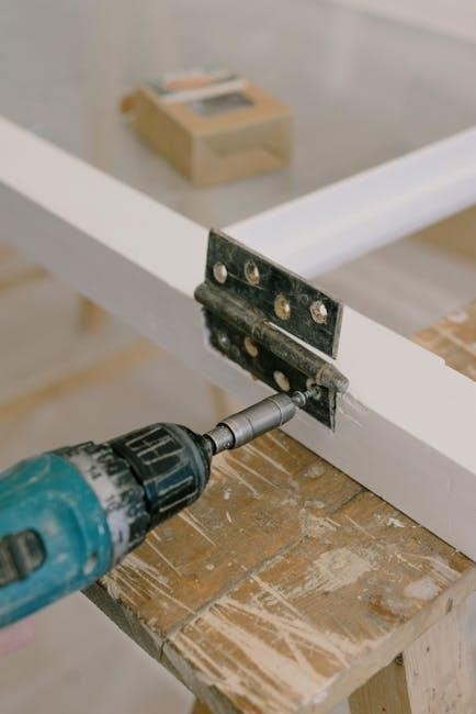
Before initiating programming, ensure the keypad has fresh batteries․ A low battery can cause inconsistent behavior and programming failures․ Familiarize yourself with the keypad’s layout, identifying the buttons for programming, clear, and entry․ Most keypads require pressing a “Learn” or “Program” button on both the keypad and the garage door opener motor unit itself to establish communication․ Refer to your garage door opener’s manual for the precise location of this button, as it varies by brand and model․

Understanding the “Learn” Button Location

Locating the “Learn” button is paramount for successful keypad programming․ This button establishes a connection between your Clicker keypad and the garage door opener motor unit․ Its position isn’t standardized; it varies significantly depending on the garage door opener’s brand and model․ Typically, you’ll find it on the back or side of the motor unit housing, often near the antenna wire․

It’s frequently a small, colored button – often yellow, orange, or purple – and may be recessed to prevent accidental activation․ Consult your garage door opener’s manual for a precise diagram illustrating its location; Some openers require removing the light cover to access the “Learn” button․ Pressing and releasing this button initiates a short window of time – usually 30 seconds – for programming the keypad․

Programming with Existing Remote

Utilizing an existing remote simplifies keypad programming․ After locating and activating the “Learn” button on your garage door opener motor unit, quickly enter programming mode on the keypad․ Most Clicker keypads require pressing a “Learn” or “Program” button followed by entering a temporary code․

Within the 30-second window, press and hold the button on your working remote․ The keypad should then recognize the remote’s signal and associate it with a PIN code․ Repeat this process for each additional remote you wish to link to the keypad․ This method bypasses the need to manually input radio frequency codes, streamlining the setup process and ensuring compatibility․

Step-by-Step Programming Guide

Initiate programming by accessing the keypad’s mode, inputting your desired PIN, and confirming it for secure garage access—a straightforward, user-friendly process․

Follow the manual’s instructions carefully, ensuring a successful connection between the keypad and your garage door opener system․

Entering Programming Mode

To begin programming your Clicker keypad, locate the “Learn” button on your garage door opener motor unit – its position varies by brand, so consult your opener’s manual․ Pressing this button activates a short window, typically 30 seconds, for programming․

Immediately after activating the “Learn” button, return to your keypad․ Most keypads require you to enter a sequence, often involving pressing the “#” or “*” key, or a combination, to initiate programming mode․ The keypad display will usually indicate it’s ready with a flashing light or a specific message․

Refer to your Clicker keypad’s manual for the exact sequence, as it differs between models․ Speed is key; you must enter programming mode before the 30-second window closes on the garage door opener unit;

Entering Your Desired PIN Code

Once in programming mode, the keypad will prompt you to enter your new PIN code․ Choose a four-digit code that is easy for you to remember, but difficult for others to guess․ Avoid obvious sequences like “1234” or your birthdate for security reasons․

Carefully enter each digit, observing the keypad display to confirm accuracy․ Some keypads may display asterisks (*) instead of the numbers as you enter them, enhancing privacy․ After entering the final digit, the keypad may require you to press a confirmation key, such as “#” or “Enter”․

Double-check the entered code before confirming, as incorrect entry may necessitate repeating the entire programming process․

Confirming the PIN Code

After entering your desired PIN, the keypad typically requires confirmation to finalize the programming․ This often involves re-entering the same four-digit code a second time․ Pay close attention to ensure both entries match exactly; discrepancies will trigger an error, forcing you to start over․

Some systems may signal successful programming with a visual cue, like a flashing light or a brief display message․ Others might activate the garage door opener briefly to confirm functionality․

Test the new PIN code immediately by entering it on the keypad to verify it correctly operates the garage door․ If it fails, repeat the programming steps carefully․

Troubleshooting Common Issues

Common problems include unresponsive keypads, incorrect PIN errors, and forgotten codes; these often stem from battery issues or programming glitches requiring reset steps․

Decades of use can cause remote failures, but troubleshooting steps can often restore functionality before requiring replacement parts or professional help․

Keypad Not Responding

If your Clicker keypad isn’t responding, begin with the simplest solutions․ First, verify the batteries are fresh and correctly installed; low battery power is a frequent culprit․ Ensure there isn’t any physical obstruction – dirt, debris, or ice – interfering with the buttons․

Next, check for interference from other wireless devices․ Sometimes, signals can clash, causing temporary malfunctions․ Try temporarily turning off nearby devices to see if that resolves the issue․ If the keypad still fails to respond, attempt a reset by removing the batteries for a minute, then reinserting them․

Consult your garage door opener’s manual for specific reset instructions, as procedures can vary by brand․ If these steps don’t work, the keypad itself may be faulty and require replacement․

Incorrect PIN Code Errors

Encountering “Incorrect PIN Code” errors on your Clicker keypad is frustrating, but often easily resolved․ Double-check that you’re entering the correct sequence, paying close attention to the numbers․ Remember that PIN codes are case-sensitive on some models, though this is less common with garage door keypads․

If you’ve recently changed the PIN, ensure you’re using the new code and haven’t reverted to the old one by mistake․ Repeated incorrect attempts may temporarily lock the keypad as a security measure; wait a few minutes before trying again․

If you’ve forgotten your PIN, refer to the manufacturer’s instructions for resetting it, which usually involves a specific button combination or accessing the opener’s control panel․

Lost or Forgotten PIN Code

Misplacing or forgetting your Clicker garage door keypad PIN code is a common issue, but thankfully, there are recovery options․ Most systems don’t store the PIN in a readily accessible format for security reasons․ Typically, resetting the PIN requires accessing the garage door opener’s “Learn” button – its location varies by brand, so consult your manual;

Pressing and holding the “Learn” button initiates a reset process, often requiring you to enter a new PIN code․ Some models may necessitate a factory reset, erasing all existing codes․

If you’re unable to reset the code yourself, contacting the manufacturer’s support or a professional garage door service is recommended․

Advanced Keypad Features

Modern Clicker keypads offer multiple user codes, temporary access options for guests, and a vacation mode for enhanced security while you’re away․

These features provide flexibility and control, allowing customized access and peace of mind for your property․

Multiple User Codes

Many Clicker keypad systems allow programming several unique PIN codes, granting individual access to family members, trusted friends, or service providers․ This eliminates the need to share a single code, enhancing security and accountability․

Each user can have a distinct code, and the keypad’s memory typically accommodates a substantial number of entries․ This feature is particularly useful for households with varying access needs or for monitoring who enters and exits the garage․

The programming process for adding or deleting user codes is usually straightforward, accessible through the keypad’s interface․ Refer to your specific model’s manual for detailed instructions on managing multiple user PINs, ensuring a secure and convenient access solution․

Temporary Access Codes

Certain Clicker keypad models offer the functionality to create temporary, time-sensitive PIN codes․ This is ideal for granting access to guests, delivery personnel, or service technicians for a limited duration, boosting security․

These codes can be programmed to expire automatically after a pre-defined period – hours, days, or even a single use – eliminating the need to manually delete them later․ This feature minimizes the risk of unauthorized access if a temporary code is compromised․

Consult your keypad’s manual for specific instructions on setting up and managing temporary codes, including how to define the expiration timeframe․ This provides a convenient and secure way to control garage access without permanent code changes․

Vacation Mode Activation

Many Clicker garage door opener keypads include a “Vacation Mode” designed to enhance security during extended absences․ This feature typically disables the keypad’s functionality, preventing access via PIN code while you’re away, offering peace of mind․

Activating Vacation Mode often requires a specific sequence of button presses on the keypad itself, as detailed in your owner’s manual․ It’s crucial to understand this process before leaving for your trip to ensure proper activation․

Remember that Vacation Mode usually deactivates the keypad entirely; remote controls may still function depending on your system’s configuration․ Always verify your system’s behavior before relying solely on Vacation Mode for security․

Compatibility and Universal Keypads

Universal keypads promise broad compatibility, but verifying your garage door opener’s brand is essential for successful integration and optimal functionality․

While convenient, universal keypads have limitations; they may not support all features or brands, requiring careful consideration before purchase․

Identifying Your Garage Door Opener’s Brand

Accurately identifying your garage door opener’s brand is the foundational step towards successful keypad programming and compatibility assessment․ Often, the brand name is prominently displayed on the motor unit itself, typically located within the garage․ Look for labels, stickers, or embossed markings on the unit’s housing․

Common brands include Chamberlain, LiftMaster, Craftsman, Genie, and Overhead Door․ If the brand isn’t immediately visible, consult the owner’s manual for your garage door opener․ The manual will definitively state the manufacturer and model number․

Knowing the model number is also incredibly helpful, as it allows you to pinpoint specific compatibility information and access detailed programming instructions from the manufacturer’s website․ Online resources and forums can also assist in identification if you’re still unsure․

Using Universal Keypads with Different Brands

Universal keypads are designed for broad compatibility, aiming to work across multiple garage door opener brands like Chamberlain, LiftMaster, and Genie․ However, “universal” doesn’t guarantee seamless operation with every system․ Programming typically involves a “learning” process where the keypad mimics the signal of your existing remote․

Success hinges on the keypad supporting the frequency used by your opener – commonly 310MHz, 390MHz, or rolling code technology․ Carefully follow the keypad’s instructions, often requiring you to enter programming mode on both the keypad and the garage door opener itself․

Be aware that some older or less common brands may present compatibility challenges, potentially requiring a brand-specific keypad for reliable functionality․

Limitations of Universal Keypads

Despite their convenience, universal keypads aren’t without limitations․ Older garage door openers, particularly those lacking rolling code technology, may be incompatible, creating security vulnerabilities․ Some advanced features, like those found on newer LiftMaster or Chamberlain models, might not be fully replicated by a universal keypad․

Troubleshooting can be more complex, as pinpointing the source of an issue – the keypad, the opener, or the compatibility itself – requires careful diagnosis․ Furthermore, universal keypads may not support all the programming options available with a brand-specific model․

Ultimately, while a cost-effective solution, a universal keypad might necessitate compromises in functionality or security․

Battery Replacement and Maintenance

Regular battery checks are vital for consistent keypad operation; typically, replacements are needed every 1-2 years, depending on usage and environmental factors․

Gentle cleaning with a damp cloth preserves functionality, while shielding the keypad from direct weather exposure extends its lifespan and reliability․

Battery Type and Replacement Frequency

Most Clicker keypad models utilize a 9-volt alkaline battery, though some newer versions may require a CR2032 button cell battery – always confirm the correct type in your owner’s manual․ Battery life is significantly impacted by usage frequency; homes with multiple users or frequent garage access will experience shorter intervals between replacements․

Generally, you can expect to replace the battery every 1 to 2 years under normal conditions․ However, extreme temperatures (both hot and cold) can reduce battery performance․ A noticeable decrease in keypad responsiveness, dimming of the display, or difficulty entering a PIN code are all indicators that a battery change is needed․ Proactive replacement prevents unexpected outages and ensures continued access to your garage․

Keep a fresh battery on hand for quick swaps, avoiding prolonged inconvenience․

Cleaning the Keypad

Regular cleaning maintains your Clicker keypad’s functionality and appearance․ Disconnect the power source – either by removing the battery or switching off the garage door opener – before cleaning․ Use a soft, slightly damp cloth to wipe down the keypad surface․ Avoid abrasive cleaners, solvents, or excessive moisture, as these can damage the electronic components or keypad buttons․

For stubborn dirt or grime, a mild soap solution can be used, but ensure the cloth is only damp, not wet, and wipe thoroughly with a dry cloth afterward․ Pay attention to the spaces around the buttons, where debris can accumulate․ Avoid spraying liquids directly onto the keypad; always apply to the cloth first․

Routine cleaning prevents sticky buttons and ensures reliable operation․

Protecting the Keypad from Weather

Exposure to the elements can significantly reduce your Clicker keypad’s lifespan․ While some keypads are weather-resistant, direct exposure to rain, snow, or extreme temperatures should be avoided․ If your keypad is mounted outdoors, ensure it’s shielded by an overhang or protective cover․

Consider a weatherproof enclosure specifically designed for garage door keypads for optimal protection․ Regularly inspect the keypad for signs of water damage, such as corrosion or swelling․ Avoid using the keypad with wet hands, and promptly dry any moisture that may accumulate․

Proper protection safeguards against malfunctions and extends the keypad’s operational life, ensuring consistent access․

Safety Considerations

Prioritize security by avoiding default PIN codes and regularly changing them․ Report lost or stolen keypads immediately to prevent unauthorized access to your home․

Security Risks of Default PIN Codes

Default PIN codes, often 1234 or similar easily guessable sequences, present a significant security vulnerability for your garage door opener․ These codes are widely known and frequently listed online, making your home an easy target for potential intruders․ Criminals actively search for garages utilizing factory settings, exploiting this oversight for quick and simple access․

Leaving the default code in place is akin to leaving your garage door unlocked․ It bypasses the intended security feature of the keypad, rendering it ineffective․ Changing the PIN to a unique, complex combination – avoiding birthdays or obvious numbers – drastically reduces the risk of unauthorized entry․ Regularly updating your PIN code further enhances security, creating a moving target for any would-be trespassers․

Regularly Changing Your PIN Code

Consistent PIN code updates are a cornerstone of maintaining garage door security․ Think of it like changing passwords for your online accounts – a proactive measure against potential breaches․ Establishing a routine, such as every three to six months, minimizes the window of opportunity for unauthorized access should your code become compromised․

Don’t simply cycle through predictable variations of your existing code․ Opt for entirely new, random combinations․ Avoid easily guessable information like birthdates or house numbers․ This practice significantly strengthens your defense against determined individuals attempting to gain entry․ A frequently altered PIN code adds a crucial layer of protection, ensuring your home remains secure․

Reporting a Lost or Stolen Keypad

Immediate action is critical if your Clicker keypad is lost or stolen․ Treat it with the same urgency as a lost house key or credit card․ The first step is to reprogram the garage door opener, effectively deactivating the missing keypad’s access․ This prevents unauthorized entry and restores your peace of mind․

Consider reporting the incident to local law enforcement, especially if you suspect theft․ While a lost keypad may be a simple misplacement, a stolen one could indicate malicious intent․ Document the date and time of the loss or theft, and any relevant details․ Contacting the manufacturer may also be advisable for further guidance and support․

Resources and Support

Manufacturer websites and manuals provide detailed programming instructions and troubleshooting․ Online forums offer community support, while professional services ensure expert repairs․

Knowledge-sharing platforms like Zhihu offer valuable insights, and Clicker Heroes communities can assist with related technical issues․

Manufacturer’s Website and Manuals

Accessing the official manufacturer’s website is the primary resource for your Clicker garage door opener keypad․ These sites typically host downloadable digital versions of your specific model’s manual, offering detailed programming steps and troubleshooting guides․ Manuals often include diagrams illustrating the “learn” button location and PIN code entry procedures․

Searching by model number ensures you find the correct documentation․ Beyond programming, manuals detail safety precautions, warranty information, and parts lists․ Many manufacturers also provide FAQ sections addressing common keypad issues․ Online support portals may offer video tutorials or live chat assistance․ Remember to register your product on the website for access to exclusive support resources and updates․

Online Forums and Communities

Dedicated online forums and communities offer a wealth of user-generated knowledge regarding Clicker garage door opener keypads․ These platforms allow you to connect with other owners, share experiences, and seek advice on programming challenges or troubleshooting issues․ Searching existing threads can often reveal solutions to common problems, bypassing the need for professional assistance․

Popular home improvement forums and garage door specific communities are excellent starting points․ When posting, provide your keypad model number for targeted help․ Be mindful of security – avoid sharing your PIN code publicly․ Clicker Heroes communities, while game-focused, demonstrate a collaborative spirit applicable to problem-solving․ Remember to verify information from forums with official sources․

Professional Garage Door Repair Services

When self-troubleshooting fails, professional garage door repair services provide expert assistance with Clicker keypad issues․ Technicians possess specialized knowledge and tools to diagnose complex problems, including wiring faults, receiver malfunctions, and compatibility concerns․ They can reprogram keypads, replace faulty components, and ensure your system operates safely and efficiently․

Choosing a reputable service is crucial; look for licensed and insured companies with positive customer reviews․ While online resources offer guidance, a professional can accurately assess the situation and offer a lasting solution․ Consider services that offer emergency support, especially if your garage door security is compromised․ Remember, attempting complex repairs yourself could void warranties․

hover 1 electric scooter manual

Hover-1 Electric Scooter Manual: A Comprehensive Guide

Hover-1 delivers innovative electric transportation, and this manual ensures safe operation of your Dream Electric Scooter. Read carefully for optimal performance!

Hover-1 welcomes you to the future of personal transportation with the Dream Electric Scooter! This innovative vehicle offers a convenient and eco-friendly way to navigate urban environments;

Before embarking on your riding journey, thoroughly familiarize yourself with this manual. It contains crucial safety guidelines, operating instructions, and maintenance tips. Failure to adhere to these instructions could result in damage, injury, or even death.

Enjoy the ride responsibly and explore the freedom the Dream Scooter provides!

Unboxing and Component Checklist

Carefully unpack your Hover-1 Dream Electric Scooter and verify all components are present. Your package should include the scooter itself, handlebars, a charging adapter, and this user manual.

Inspect each part for any shipping damage. If any components are missing or damaged, immediately contact customer support. Do not attempt to assemble or operate a damaged scooter. Retain the original packaging for potential returns or warranty claims.

Confirm all items before proceeding to assembly!

Safety Precautions and Warnings

Electric scooter use involves inherent risks. Failure to follow instructions can lead to property damage, serious injury, or even death. Always wear a helmet and appropriate safety gear.

Never operate the scooter under the influence of drugs or alcohol. Be aware of your surroundings and local traffic laws. Regularly inspect the scooter for any mechanical issues before each ride.

Prioritize safety; read this manual thoroughly before operation!

Understanding the Risks of Electric Scooter Use

Electric scooters, while convenient, present potential hazards. Collisions with pedestrians or vehicles are possible, leading to injuries. Loss of control due to speed or uneven surfaces can occur.

Mechanical failures, such as brake malfunctions, pose significant risks. Improper use or modifications can compromise safety features. Always be mindful of your environment and ride defensively.

Understanding these risks is crucial for responsible scooter operation and preventing accidents.

Importance of Reading the Manual

This manual is your guide to safely enjoying your Hover-1 Dream Electric Scooter. Failure to follow instructions can result in damage, injury, or even death. It details proper operation, maintenance, and troubleshooting procedures.

Understanding the scooter’s features and limitations is vital. Familiarize yourself with safety precautions and warnings before your first ride. Retain this manual for future reference and share it with other riders.

Prioritize safety – read and understand this manual thoroughly!

Scooter Anatomy and Key Features

Your Hover-1 Dream Electric Scooter boasts several key components. The handlebar controls manage acceleration, braking, and the display panel. This panel provides vital information like speed and battery level.

Locate the battery indicator and charging port for convenient power management. The robust frame and durable tires ensure a stable ride. The kickstand allows for easy parking. Understanding these features enhances your riding experience and safety.

Familiarize yourself with each part for optimal control!

Handlebar Controls Explained

The Hover-1 Dream Electric Scooter’s handlebar controls are intuitive for a smooth ride. The right handlebar features the throttle, controlling acceleration – gently press down to increase speed. The left handlebar houses the brake lever; squeeze firmly for effective stopping power.

Additional controls may include a headlight switch and a bell for signaling. Always practice using these controls in a safe, open area before navigating traffic. Familiarity ensures responsive handling and enhanced safety.

Display Panel Overview

The Hover-1 Dream Electric Scooter’s display panel provides crucial ride information. It prominently shows your current speed, ensuring you stay within legal limits. The battery indicator displays remaining power, preventing unexpected shutdowns. Riding mode is also indicated here – Eco, Drive, or Sport.

Some models may include additional features like odometer and trip distance. Understanding these indicators allows for informed riding decisions and optimal scooter management.

Battery Indicator and Charging Port

The Hover-1 Dream Electric Scooter features a clear battery indicator on the display panel, showing remaining charge levels. A low battery warning will illuminate when charging is needed. Locate the charging port, typically near the rear wheel, covered by a protective flap.

Only use the provided Hover-1 charger to avoid damage. Proper charging procedures, detailed later in this manual, are vital for battery longevity and performance.

Assembly Instructions

Before your first ride, some assembly is required. Carefully unpack all components and verify everything listed in the component checklist is present. Hover-1 scooters generally require attaching the handlebars to the stem, ensuring proper alignment and secure tightening.

Adjust brake cables for optimal responsiveness and install the kickstand, confirming it locks firmly into place. Refer to detailed diagrams for correct assembly.

Attaching the Handlebars

Begin by loosening the stem clamp on the scooter’s steering tube. Carefully insert the handlebars into the stem, ensuring they are centered and aligned with the front wheel. Tighten the clamp securely, but avoid over-tightening, which could damage the stem.

Verify the handlebars don’t rotate freely after tightening. Proper handlebar attachment is crucial for safe steering and control during operation.

Adjusting Brake Cables

Inspect brake cables for proper tension; they should not be too loose or too tight. If adjustment is needed, locate the barrel adjuster on the brake lever or near the caliper. Turning the adjuster clockwise increases tension, while counterclockwise decreases it.

Ensure both brakes engage firmly when the levers are squeezed. Regularly check cable condition for fraying or damage, replacing as needed for optimal braking performance and safety.

Kickstand Installation

The kickstand typically attaches to the scooter frame near the rear wheel using bolts and washers. Align the kickstand with the mounting holes and secure it firmly with the provided hardware.

Ensure the kickstand is properly tightened to prevent wobbling or detachment during use. Test the kickstand’s stability by gently rocking the scooter side to side after installation, verifying secure mounting.

Operating Instructions

Before riding, ensure the scooter is on a flat, stable surface. Press the power button to initiate operation; the display panel will illuminate. Use the throttle to accelerate, and gently apply the brake lever to decelerate or stop.

Familiarize yourself with the riding modes and speed settings for a controlled experience. Always maintain a safe speed and be aware of your surroundings while operating the Hover-1 scooter.

Powering On and Off

To power on your Hover-1 scooter, firmly press and hold the power button, typically located on the handlebar, for approximately two seconds. The display panel will activate, indicating the scooter is ready for use. To power off, repeat this process – press and hold the power button for two seconds.

Ensure the scooter is stationary before powering on or off to prevent accidental movement. Always check the battery indicator before each ride.

Acceleration and Braking Techniques

Hover-1 scooters utilize a throttle, usually a thumb lever or twist-grip, for acceleration. Gently apply pressure to increase speed; release to decelerate. For braking, engage the brake levers located on the handlebars. Apply pressure smoothly and progressively for controlled stopping.

Practice in a safe, open area. Avoid sudden acceleration or braking, especially on slick surfaces. Remember, braking distance increases with speed.

Riding Modes and Speed Settings

Your Hover-1 scooter may feature multiple riding modes – typically Eco, Drive, and Sport – selectable via the display panel. Eco mode limits speed for extended range, while Sport unlocks maximum performance.

Speed settings are often adjustable within each mode. Always start in Eco mode to familiarize yourself with the scooter’s handling. Be mindful of local speed regulations and adjust accordingly for a safe and enjoyable ride.

Charging the Scooter

Proper charging is crucial for maintaining your Hover-1 scooter’s battery health and longevity. Locate the charging port, typically covered, and connect the provided charger.

Charging times vary based on battery capacity, but generally range from several to many hours. Avoid overcharging; disconnect once the indicator light signals completion. Always use the original charger to prevent damage and ensure optimal performance.

Charging Time and Battery Capacity

Hover-1 scooter charging times depend on the specific model and battery capacity. A full charge typically takes several hours, but can vary significantly. Battery capacity, measured in Amp-hours (Ah), determines the scooter’s range.

Larger Ah ratings mean longer rides. Always refer to your scooter’s technical specifications for precise charging times and battery details. Consistent, proper charging maximizes battery lifespan and performance.

Proper Charging Procedures

Hover-1 recommends using the provided charger only. Connect the charger to a standard wall outlet and the scooter’s charging port. Avoid charging in extreme temperatures or direct sunlight.

Monitor the battery indicator during charging; do not overcharge. Disconnect the charger once the indicator shows a full charge. Regular, mindful charging habits extend battery life and ensure optimal scooter functionality.

Battery Maintenance Tips

To maximize your Hover-1 scooter’s battery life, avoid fully discharging it before recharging. Store the scooter in a cool, dry place when not in use, away from extreme temperatures.

Regularly check for any signs of damage to the battery or charging port. Consistent, proper care will significantly extend the battery’s lifespan and maintain peak performance for enjoyable rides.

Maintenance and Care

Hover-1 scooters require routine upkeep for optimal performance and longevity. Regularly inspect all components, including brakes, tires, and the frame, for wear and tear.

Keep the scooter clean by wiping it down with a damp cloth. Prioritize tire pressure checks and ensure proper brake functionality. Consistent maintenance guarantees a safe and enjoyable riding experience.

Cleaning the Scooter

Hover-1 recommends regular cleaning to maintain your scooter’s appearance and functionality. Use a damp cloth to wipe down the frame, handlebars, and deck. Avoid harsh chemicals or abrasive cleaners, as these can damage the finish.

For stubborn dirt, a mild soap solution is acceptable, but ensure thorough rinsing and drying. Never submerge the scooter in water, and pay attention to electrical components.

Tire Pressure and Maintenance

Maintaining proper tire pressure is crucial for a smooth and safe ride on your Hover-1 scooter. Check tire pressure before each use, inflating to the recommended PSI (pounds per square inch) found on the tire sidewall.

Underinflated tires reduce range and increase rolling resistance. Regularly inspect tires for wear and tear, replacing them when necessary to ensure optimal performance and safety.

Checking Brake Functionality

Hover-1 prioritizes rider safety, so regularly inspect your scooter’s brakes. Before each ride, firmly apply both the front and rear brakes to ensure responsive and effective stopping power.

Check brake cables for fraying or damage, and adjust them if necessary. If brakes feel spongy or unresponsive, consult a qualified technician for repair or replacement. Consistent brake checks are vital!

Troubleshooting Common Issues

Hover-1 scooters are generally reliable, but occasional issues may arise. If your scooter won’t power on, check the battery connection and charging status. For unresponsive brakes, inspect cables and consider professional repair.

If the battery isn’t charging, verify the charger and outlet. Refer to the manual for detailed solutions and safety precautions. Don’t attempt repairs beyond your expertise!

Scooter Won’t Power On

If your Hover-1 scooter fails to power on, first ensure the battery is adequately charged by connecting it to the charger and a working outlet. Verify the power button is fully engaged. Inspect the battery connection for any loose wires or damage.

If issues persist, consult the manual for specific troubleshooting steps or contact Hover-1 support for assistance.

Brakes Not Working Properly

If your Hover-1 scooter’s brakes are unresponsive, immediately stop using it and inspect the brake cables for damage or looseness. Check the brake levers for proper engagement and adjust cable tension if necessary, referencing the assembly instructions.

Ensure no obstructions hinder brake function. If problems continue, consult a qualified technician or Hover-1 support for repair.

Battery Not Charging

If your Hover-1 scooter isn’t charging, first verify the charger is securely connected to both the scooter and a functioning power outlet. Inspect the charging port for debris or damage. Try a different outlet to rule out power source issues.

If the problem persists, the battery or charger may be faulty; contact Hover-1 support for assistance.

Warranty Information

Hover-1 provides a warranty covering defects in materials and workmanship. Coverage Details vary by product; refer to your purchase documentation for specifics. To initiate a Claim Process, contact Hover-1 customer support with proof of purchase and a description of the issue.

Limitations and Exclusions apply, including damage from misuse or accidents.

Coverage Details

Hover-1’s warranty safeguards against manufacturing defects for a specified period, typically one year from the purchase date. This coverage encompasses the scooter’s frame, motor, and electronic components under normal use. The warranty doesn’t extend to wear-and-tear items like tires or brake pads.

Damage resulting from accidents, misuse, or unauthorized modifications voids the coverage.

Claim Process

To initiate a warranty claim, contact Hover-1’s customer support with your proof of purchase and a detailed description of the issue. You may be required to provide photos or videos demonstrating the defect. Hover-1 will assess the claim and, if approved, provide instructions for returning the scooter.

Shipping costs for warranty repairs are typically the responsibility of the customer, initially.

Limitations and Exclusions

This warranty does not cover normal wear and tear, accidents, misuse, abuse, or unauthorized modifications. Damage resulting from improper maintenance, failure to follow instructions, or acts of nature are also excluded. Hover-1 is not liable for incidental or consequential damages.

The warranty is void if the scooter is used for commercial purposes or subjected to extreme conditions.

Technical Specifications

Hover-1 Ultra Electric Scooter boasts a maximum speed of 18.6 mph and a range up to 15.5 miles, dependent on rider weight and conditions. It supports a weight capacity of 220 lbs.

The scooter features a 36V, 5.8Ah lithium-ion battery and a 350W motor, delivering reliable performance. Detailed specifications may vary slightly by model; consult packaging for precise details.

Maximum Speed and Range

The Hover-1 Ultra Electric Scooter achieves a top speed of 18.6 miles per hour, providing a swift and efficient commute. Range capabilities extend up to 15.5 miles on a single full charge, though this is influenced by factors like rider weight,

terrain, and riding style. Always prioritize safety and adhere to local speed regulations while enjoying the scooter’s performance.

Weight Capacity

Hover-1 Electric Scooters are engineered for riders within a specific weight range to ensure optimal safety and performance. The maximum weight capacity for the Ultra model is 220 pounds (100 kilograms).

Exceeding this limit can compromise the scooter’s stability, braking effectiveness, and overall control, potentially leading to accidents or damage. Always verify your weight before operation.

Motor and Battery Details

The Hover-1 Ultra Electric Scooter is powered by a robust 36V, 350W motor, delivering reliable performance for various terrains. It utilizes a high-capacity 36V 6.0Ah lithium-ion battery, providing an extended range on a single charge.

Battery life varies based on rider weight, speed, and road conditions. Proper battery maintenance, as outlined in this manual, is crucial for longevity and optimal performance.

Legal Considerations and Local Regulations

Electric scooter laws vary significantly by location. Always check and adhere to your local regulations regarding scooter usage, including permitted riding areas and speed limits.

Hover-1 strongly recommends wearing a helmet and other appropriate safety gear while riding. Some jurisdictions legally require these protective measures. Be aware of pedestrian traffic and prioritize safety at all times.

Scooter Laws in Your Area

Electric scooter regulations are constantly evolving, differing greatly between cities and states. Before operating your Hover-1 scooter, research local ordinances concerning where you can legally ride – sidewalks, bike lanes, or roads.

Understand speed restrictions, potential licensing requirements, and any age limitations. Ignoring these laws can result in fines or legal consequences. Stay informed and ride responsibly to ensure compliance.

Helmet and Safety Gear Requirements

Safety is paramount when riding your Hover-1 electric scooter. A properly fitted helmet is essential, significantly reducing the risk of head injury in case of a fall. Consider additional protective gear like knee and elbow pads, and wrist guards for enhanced safety.

Bright clothing increases visibility, especially during low-light conditions. Always prioritize personal protection to minimize potential injuries and enjoy a safer riding experience.

Where You Can Ride

Understanding local regulations is crucial before operating your Hover-1 electric scooter. Always check and adhere to scooter laws in your specific area, as they vary significantly. Generally, avoid riding on sidewalks, pedestrian zones, and highways.

Designated bike lanes and roads with lower speed limits are typically suitable. Prioritize safe locations, avoiding areas with heavy traffic or hazardous conditions. Responsible riding ensures both your safety and compliance.

elna sewing machine manual

Elna Sewing Machine Manual: A Comprehensive Guide

Elna sewing machines‚ originating in Switzerland and now under Janome ownership‚ boast a rich history. This guide explores models from 1940-1978‚
covering mechanical to highly computerized options like the eXcellence series. Understanding your Elna requires accessing the correct manual for optimal performance and longevity.

Historical Overview of Elna Sewing Machines

Elna’s story began in 1934 with Dr. Ramon Casas Robert’s groundbreaking prototype‚ introducing the innovative free-arm design. This feature‚ allowing easy fabric maneuvering – particularly sleeves and pant legs – revolutionized sewing. The true genesis arrived in 1940 with the Elna 1‚ the world’s first compact‚ portable‚ electric sewing machine also featuring this free-arm functionality. Uniquely‚ its metal carrying case unfolded to become a functional sewing table‚ enhancing convenience.

Throughout the subsequent decades‚ Elna consistently pushed boundaries‚ producing a diverse range of models between 1940 and 1978. These included the Air Electronic and Automatic series‚ alongside classic lines like Grasshopper‚ Elnita‚ Lotus‚ Special‚ Stella‚ Straight Stitch‚ Supermatic‚ Top Special‚ and Zig Zag. Elna machines evolved from purely mechanical operation to incorporating computerized technology‚ catering to a widening spectrum of sewing needs and skill levels. The brand’s commitment to ease of use‚ versatility‚ and modern design cemented its place in sewing history.

The Genesis of Elna: Dr. Ramon Casas Robert’s Innovation (1934)

The foundation of Elna lies in the ingenuity of Dr. Ramon Casas Robert‚ whose pioneering work in 1934 resulted in the first prototype Elna sewing machine. This wasn’t merely an incremental improvement; it represented a fundamental shift in sewing machine design with the introduction of the free-arm concept. Unlike conventional machines with flatbeds‚ the Elna prototype featured a portion of the machine bed extending outwards.

This seemingly simple alteration unlocked significant advantages for sewers. The free-arm configuration provided unobstructed access to fabric‚ making it dramatically easier to manipulate cuffs‚ collars‚ and other cylindrical garment pieces. Dr. Robert’s vision wasn’t just about functionality; it was about enhancing the sewing experience. He aimed to create machines that were intuitive‚ adaptable‚ and reflective of modern design principles. This initial innovation laid the groundwork for Elna’s future success and established its reputation for forward-thinking engineering.

Elna 1: The First Portable Electric Sewing Machine (1940-1952)

In 1940‚ Elna revolutionized home sewing with the launch of the Elna 1‚ widely recognized as the first compact‚ portable‚ and electric sewing machine featuring a free arm. This wasn’t just a scaled-down version of existing machines; it was a completely reimagined design prioritizing convenience and accessibility; The Elna 1 cleverly incorporated its metal carrying case into a functional sewing table when unfolded‚ eliminating the need for a separate workspace.

Throughout its production run‚ spanning from 1940 to 1952‚ the Elna 1 underwent minor refinements‚ but its core design remained remarkably consistent. This speaks to the effectiveness of Dr. Robert’s original vision. The machine’s portability opened up sewing to a wider audience‚ allowing enthusiasts to pursue their craft anywhere with an electrical outlet. The Elna 1 quickly became a symbol of modern convenience and Swiss engineering‚ establishing Elna as a leading brand in the sewing machine industry.

Key Features of Early Elna Models (1940-1978)

Early Elna sewing machines‚ produced between 1940 and 1978‚ consistently prioritized user-friendliness‚ versatility‚ and modern design. The hallmark free-arm feature‚ pioneered with the Elna 1‚ remained a central element‚ facilitating effortless sewing of cuffs‚ sleeves‚ and pant legs. Beyond this‚ Elna models showcased robust construction and reliable performance‚ earning a reputation for durability.

The lineup included diverse series like Grasshopper‚ Elnita‚ Lotus‚ Special‚ Stella‚ Straight Stitch‚ Supermatic‚ Top Special‚ and Zig Zag‚ each catering to different sewing needs and skill levels. Many models featured innovative mechanisms for automatic stitch selection and length adjustment. Elna’s commitment to quality materials and precision engineering ensured smooth operation and consistent stitch quality. These machines weren’t simply tools; they were designed to inspire creativity and make sewing an enjoyable experience.

Understanding Elna Sewing Machine Models

Elna offers a diverse range‚ from mechanical simplicity to advanced computerized options. Explore the eXplore‚ eXperience‚ eXcellence‚ eXpressive‚ and eXtend series to find your perfect match.

Mechanical Elna Sewing Machines: A Detailed Look

Elna’s early mechanical models‚ particularly those produced between 1940 and 1978‚ represent a cornerstone of sewing innovation. The Elna 1‚ launched in 1940‚ was revolutionary as the first compact‚ portable‚ electric machine featuring a free-arm design. This free-arm functionality‚ allowing easy maneuvering of cylindrical items like sleeves‚ remains a hallmark of many Elna machines.

These machines‚ including the Grasshopper‚ Lotus‚ Special‚ Stella‚ Straight Stitch‚ Supermatic‚ Top Special‚ and Zig Zag series‚ prioritize user-friendliness and durability. Manuals for these models typically detail threading procedures‚ stitch selection guides‚ bobbin winding instructions‚ and basic maintenance tasks like oiling and cleaning.

Understanding the mechanical components – tension discs‚ feed dogs‚ presser foot mechanisms – is crucial for troubleshooting. Common issues addressed in manuals include thread breakage‚ skipped stitches‚ and uneven fabric feeding. Regular maintenance‚ as outlined in the manual‚ ensures longevity and consistent performance. Elna mechanical machines offer a tactile and reliable sewing experience‚ favored by both beginners and experienced sewists.

Computerized Elna Sewing Machines: Features and Benefits

Elna’s computerized sewing machines‚ including the eXplore and eXcellence series‚ represent a significant leap in sewing technology. These models offer a wider range of stitch options‚ automated features‚ and enhanced precision compared to their mechanical counterparts. Manuals for computerized Elna machines detail navigating the digital interface‚ selecting pre-programmed stitches‚ utilizing automatic buttonhole functions‚ and customizing stitch settings.

Benefits include increased speed‚ consistent stitch quality‚ and the ability to tackle complex sewing projects with ease. Features often include LCD screens‚ memory functions for saving personalized stitch combinations‚ and adjustable sewing speeds. Troubleshooting guides within the manuals address error messages‚ sensor malfunctions‚ and connectivity issues.

Understanding the computerized components – the control panel‚ the stitch memory‚ and the motor – is vital for optimal use. Regular software updates‚ as recommended in the manual‚ ensure compatibility and access to new features. Elna’s computerized machines empower sewists with greater creative control and efficiency.

Premium Computerized Elna Sewing Machines: The eXcellence Series

The eXcellence series represents Elna’s pinnacle of computerized sewing machine technology. Manuals for these premium models detail advanced features like extended stitch libraries‚ enhanced editing capabilities‚ and sophisticated automation. These machines cater to serious sewists and quilting enthusiasts demanding precision and versatility.

Key benefits include a larger workspace‚ improved needle threading systems‚ and advanced sensor technology for fabric handling. Manuals emphasize utilizing the series’ unique features‚ such as pattern drafting tools‚ automatic thread trimming‚ and customizable stitch density. Troubleshooting sections address complex error codes and potential issues with the advanced sensors.

eXcellence series manuals also cover connectivity options‚ allowing for software updates and pattern downloads. Understanding the machine’s memory functions‚ stitch customization options‚ and the advanced foot control system is crucial. Regular maintenance‚ as outlined in the manual‚ ensures longevity and peak performance of these sophisticated machines.

Embroidery Machines: Elna’s eXpressive Range

Elna’s eXpressive embroidery machines offer a dedicated solution for intricate designs and personalized creations. The accompanying manuals are essential for navigating the specialized software and hardware components. These guides detail hoop selection‚ stabilizer usage‚ and thread compatibility for optimal embroidery results.

Manuals emphasize digitizing techniques‚ importing embroidery files‚ and editing designs within the machine’s software. Understanding stitch density‚ underlay settings‚ and color changes is crucial for achieving professional-looking embroidery. Troubleshooting sections address common issues like thread breaks‚ skipped stitches‚ and fabric puckering.

The eXpressive range manuals also cover maintenance procedures specific to embroidery machines‚ including cleaning the bobbin area and lubricating moving parts. Detailed diagrams illustrate proper needle threading and bobbin winding techniques. Mastering the machine’s built-in design library and connectivity options unlocks the full creative potential of these specialized machines.

Overlock and Coverstitch Machines: The eXtend Series

Elna’s eXtend series of overlock and coverstitch machines are designed for professional-quality seam finishing and garment construction. The corresponding manuals are vital for understanding the unique threading paths and adjustments required for these specialized machines. They detail the differences between overlock‚ coverstitch‚ and chain stitch settings.

Manuals provide step-by-step instructions for threading each looper and needle‚ emphasizing the importance of correct thread tension. Troubleshooting guides address common issues like skipped stitches‚ uneven seams‚ and fabric gathering. Understanding differential feed and stitch length adjustments is crucial for achieving desired results on various fabric types.

Maintenance sections cover cleaning lint buildup‚ oiling moving parts‚ and replacing blades. Diagrams illustrate proper needle and looper replacement techniques. Mastering the eXtend series requires careful study of the manual to unlock its full potential for creating durable and beautifully finished garments.

Popular Elna Sewing Machine Series

Elna series like 3000‚ 3230‚ and 6005 are popular. Their manuals offer troubleshooting‚ maintenance‚ and usage guides. Accessing the correct manual ensures optimal machine performance.

Elna 3000‚ 3005‚ 3210: Common Issues and Solutions

Elna 3000‚ 3005‚ and 3210 series machines‚ while reliable‚ can experience common issues. Threading problems are frequent; ensure the thread path is clear and the presser foot is up. Bobbin winding difficulties often stem from incorrect bobbin insertion or tension adjustments – consult your manual for diagrams.

Skipped stitches can indicate a dull or incorrect needle type for the fabric. Regularly changing the needle is crucial. Tension imbalances cause looping or puckering; adjust the upper and lower tension dials incrementally‚ testing on scrap fabric after each adjustment.

If the machine jams‚ stop immediately! Do not force it. Remove the needle plate and carefully clear any tangled thread or fabric. For motor issues‚ check the power cord and ensure the foot pedal is firmly connected. Always refer to your specific model’s manual for detailed troubleshooting steps and safety precautions. Online resources and Elna support can also provide assistance.

Elna 3230‚ 5100‚ 6001: Troubleshooting Guide

Elna 3230‚ 5100‚ and 6001 models‚ offering increased features‚ may present unique challenges. Error messages on computerized models require referencing the manual’s code list for specific diagnoses. A common issue is the needle breaking; this often indicates incorrect needle size‚ bent needle‚ or forcing the fabric.

If the machine stops mid-stitch‚ check for tangled bobbin thread or a jammed needle plate. Ensure the presser foot pressure is appropriately adjusted for the fabric weight. Uneven stitching can be caused by improper tension settings or a poorly wound bobbin.

For computerized models‚ software glitches can occur. Try restarting the machine or resetting it to factory settings (refer to the manual!). Always unplug the machine before performing any internal maintenance. Elna’s online support and model-specific manuals are invaluable resources for resolving complex issues and maintaining optimal performance.

Elna 6003 Q & QD‚ 6004: Manual Access and Support

Accessing the correct manual for Elna 6003 Q‚ QD‚ and 6004 models is crucial for maximizing their capabilities. Elna provides online resources‚ but locating the specific manual requires the exact model number. Many third-party websites archive older manuals‚ offering downloadable PDFs.

These models‚ known for their versatility‚ benefit from understanding the manual’s sections on stitch selection‚ presser foot usage‚ and maintenance. Diagrams illustrating threading paths and bobbin winding are particularly helpful.

Beyond the manual‚ Elna’s support network offers assistance. Check the official Janome website (as Elna is now a Janome brand) for FAQs and troubleshooting guides. Online sewing communities and forums dedicated to Elna machines provide peer-to-peer support and shared solutions to common problems. Remember to always refer to your manual first!

Elna 6005 Heirloom Edition: Unique Features and Usage

The Elna 6005 Heirloom Edition stands out with features designed for quilters and those preserving textile traditions. This model often includes a wider variety of decorative stitches and specialized presser feet‚ enhancing creative possibilities. The manual details these unique offerings‚ explaining their optimal usage for heirloom projects.

Understanding the stitch settings for different fabric weights is vital. The manual provides guidance on adjusting tension and stitch length for flawless results. Utilizing the included accessory kit – often containing quilting rulers and appliqué feet – requires careful study of the manual’s illustrations.

Proper maintenance‚ as outlined in the manual‚ ensures the longevity of this special edition. Regular cleaning and oiling are essential. Explore the manual’s troubleshooting section for solutions to common issues‚ preserving the Elna 6005’s performance for generations.

Accessing Elna Sewing Machine Manuals

Elna manuals are vital for machine operation and maintenance. Online resources and model-specific searches are key to locating the correct documentation.
Understanding manual sections ensures optimal sewing experiences.

Online Resources for Elna Manuals

Finding the correct Elna sewing machine manual online is often the quickest and most convenient method. Several websites specialize in hosting vintage and current manuals for various sewing machine brands‚ including Elna. A dedicated search on platforms like ManualsLib‚ or directly through the Janome website (as Janome now owns Elna) can yield positive results.

Many sewing enthusiasts have also created independent websites and forums dedicated to Elna machines‚ where users frequently share scanned copies of manuals. These community-driven resources can be invaluable‚ especially for older or less common models. YouTube also hosts numerous video tutorials demonstrating machine operation and troubleshooting‚ often referencing specific manual instructions.

When searching‚ be prepared to utilize your machine’s specific model number. Elna produced a wide range of models – from the early Elna 1 to the more recent eXpressive and eXtend series – and each requires its corresponding manual. Accurate model identification is crucial for downloading the correct documentation and ensuring proper machine usage. Remember to verify the source’s reliability before downloading any files.

Locating Manuals by Model Number

Successfully finding your Elna sewing machine manual hinges on accurately identifying the model number. This number is typically located on a metal plate affixed to the machine itself‚ often on the underside or back. Common Elna series include the 3000‚ 3230‚ 6000‚ and 6005 lines‚ each with variations denoted by additional numbers or letters (e.g.‚ Elna 6003 QD).

Once you have the complete model number‚ input it directly into search engines alongside terms like “manual‚” “instruction book‚” or “user guide.” Prioritize searches on the Janome website‚ as they are the current owners of Elna and often archive older manuals. Websites specializing in sewing machine manuals‚ such as ManualsLib‚ are also excellent resources.

If the initial search proves unsuccessful‚ try variations of the model number‚ omitting letters or using abbreviations. Remember that Elna produced machines under different names‚ like Elnita‚ so including these terms in your search may broaden the results. Precise model number identification is the key to unlocking the correct documentation for your specific Elna machine.

Understanding Manual Sections and Diagrams

Elna sewing machine manuals are structured to guide users through all aspects of operation and maintenance. Typically‚ you’ll find sections covering initial setup‚ threading procedures (upper and bobbin)‚ stitch selection‚ and basic sewing techniques. Dedicated chapters explain specialized features‚ like free-arm sewing – a hallmark of early Elna models – and accessory usage.

Pay close attention to the diagrams. Elna manuals heavily rely on visual aids to illustrate threading paths‚ component locations‚ and maintenance procedures. These diagrams are crucial for understanding how the machine functions internally. Troubleshooting sections often include exploded views of key mechanisms‚ aiding in identifying and resolving common issues.

Familiarize yourself with the safety precautions outlined in the manual before operating the machine. Understand the function of each control and lever. Regularly consult the manual for recommended lubrication points and cleaning procedures to ensure your Elna machine continues to perform optimally for years to come.

poulan chainsaw repair manual pdf

Poulan Chainsaw Repair Manual PDF: A Comprehensive Guide

Accessing a Poulan Chainsaw Repair Manual PDF unlocks detailed service information, aiding maintenance and repairs․ These manuals, available for download, cover various models, offering parts diagrams and instructions․

Understanding Poulan Chainsaw Models Covered

Poulan manufactured a wide array of chainsaws, and repair manuals often cater to specific model ranges․ Common models frequently covered include the 1950, 1975, 2050, 2055, 2075, 2150, 2155, 2175, 2350, and 2375 series․ The 2150PR is also a frequently documented model․

However, coverage can vary significantly between PDF manuals․ Some manuals are universal, addressing core components across multiple models, while others are highly specific․ Before downloading, verify the manual explicitly lists your chainsaw’s model number․ Service manuals may also differentiate between standard Poulan and Poulan Pro versions, requiring separate documentation․ Always cross-reference the model number to ensure accurate repair instructions and parts identification․

Locating the Correct PDF Manual

Finding the right Poulan Chainsaw Repair Manual PDF often starts with online searches․ Websites specializing in manuals, like eManuals, frequently host these documents for download, sometimes for a fee․ Alternatively, searching directly for “Poulan [model number] repair manual PDF” yields targeted results․

Parts websites, such as MyMowerParts․com, may also offer manuals as a resource for customers․ Be cautious of unofficial sources; prioritize reputable sites to ensure the PDF is accurate and complete․ Always verify the manual corresponds to your specific model number before relying on its service instructions․ Checking forums dedicated to chainsaw repair can also uncover direct download links or user recommendations․

Safety Precautions Before Repair

Prior to any Poulan Chainsaw repair, stringent safety measures are crucial․ Disconnect the spark plug wire to prevent accidental starting – a vital step detailed in most repair manuals․ Always wear appropriate personal protective equipment (PPE), including safety glasses, gloves, and sturdy footwear․

Ensure the chainsaw is on a stable, flat surface․ Never work on a chainsaw while fatigued or under the influence of medication․ Refer to your Poulan owner’s manual for specific warnings and safety guidelines․ Be mindful of sharp chain and bar edges․ Proper ventilation is essential when working with fuels and solvents․ Following these precautions, outlined in the PDF manual, minimizes risk during service․

Essential Tools for Poulan Chainsaw Repair

Successfully tackling Poulan Chainsaw repairs requires a specific toolkit․ A comprehensive repair manual PDF will often list these necessities․ Essential tools include a socket set, screwdrivers (Phillips and flathead), pliers, and wrenches; A torque wrench is vital for reassembling components to the correct specifications․

Specialized tools like a carburetor adjustment tool, a chain breaker, and a file for sharpening the chain are also highly recommended․ A multimeter is useful for diagnosing ignition problems․ Access to a parts diagram (often found within the manual) aids in identifying components․ Having these tools readily available streamlines the service process, as detailed in the Poulan documentation․

Understanding Chainsaw Components

A Poulan Chainsaw Repair Manual PDF emphasizes the importance of knowing your chainsaw’s anatomy․ Key components include the engine, fuel system, and ignition system․ The engine provides power, while the fuel system delivers the air-fuel mixture․ The ignition system initiates combustion․

Beyond these, understand the role of the chain, bar, sprocket, and recoil starter․ Manuals often feature exploded views and parts diagrams, clarifying component relationships․ Familiarity with these parts, as detailed in the Poulan documentation, is crucial for effective service and troubleshooting․ Knowing how each part functions allows for accurate diagnosis and repair, maximizing the chainsaw’s lifespan․

The Engine System

The Poulan Chainsaw Repair Manual PDF details the engine system as the core power source․ Typically, these chainsaws utilize a two-stroke engine, requiring a precise fuel-oil mixture․ Manuals provide specifications for this ratio, crucial for proper lubrication and preventing damage․

Understanding piston, cylinder, and crankshaft function is vital․ The PDF will illustrate these components and their interaction․ Troubleshooting sections cover issues like compression loss and overheating․ Detailed diagrams aid in disassembly and reassembly․ Proper engine maintenance, as outlined in the Poulan documentation, ensures optimal performance and extends the engine’s life․ Regular inspection and cleaning are also emphasized within the repair manual․

The Fuel System

The Poulan Chainsaw Repair Manual PDF dedicates significant attention to the fuel system, vital for engine operation․ It details the fuel tank, fuel lines, fuel filter, and carburetor components․ Manuals emphasize the importance of using the correct fuel-oil mixture for two-stroke engines, preventing damage and ensuring efficient combustion․

Troubleshooting sections address common issues like fuel leaks, clogged fuel filters, and carburetor malfunctions․ Detailed exploded views illustrate each part’s location and assembly․ The PDF provides step-by-step instructions for carburetor cleaning and adjustment, crucial for optimal performance․ Proper fuel system maintenance, as outlined in the Poulan documentation, is key to reliable operation and longevity․ Always refer to the manual for specific model requirements․

The Ignition System

The Poulan Chainsaw Repair Manual PDF thoroughly covers the ignition system, detailing components like the ignition coil, spark plug, and flywheel․ It explains how these parts work together to create the spark necessary for combustion․ Manuals provide clear diagrams illustrating the ignition system’s layout and connections․

Troubleshooting guides within the PDF address common problems such as a weak spark or no spark at all․ Step-by-step instructions are included for testing the ignition coil and replacing the spark plug․ The Poulan documentation stresses the importance of proper spark plug gap and clean connections for optimal performance․ Referencing the manual ensures correct procedures are followed during service and repair, maintaining engine reliability․

Common Poulan Chainsaw Problems & Solutions

The Poulan Chainsaw Repair Manual PDF dedicates a significant section to diagnosing and resolving frequent issues․ Common problems like a chainsaw that won’t start, runs roughly, or has chain oiling problems are addressed with detailed solutions․ The manual guides users through troubleshooting steps, often beginning with simple checks like fuel levels and spark plug condition․

PDF versions offer specific repair procedures for each issue, including carburetor adjustments, fuel filter cleaning, and ignition system checks․ Diagrams illustrate component locations, aiding in accurate service․ The Poulan documentation emphasizes safety precautions throughout the troubleshooting process․ Utilizing the manual empowers owners to perform basic maintenance and repairs, potentially avoiding costly service calls․

Chainsaw Won’t Start

The Poulan Chainsaw Repair Manual PDF systematically addresses a “chainsaw won’t start” scenario․ Initial troubleshooting, as outlined in the manual, involves verifying fuel supply – ensuring the tank isn’t empty and the fuel line isn’t obstructed․ Next, the PDF guides users to inspect the spark plug for fouling or damage, recommending cleaning or replacement as needed․

Further diagnosis detailed within the manual includes checking the ignition system, carburetor functionality, and recoil starter mechanism․ Diagrams illustrate component locations for easier inspection․ The Poulan documentation stresses the importance of proper safety procedures when working with fuel and electrical components․ Following the manual’s step-by-step instructions can often resolve starting issues without professional service․

Chainsaw Runs Rough

A Poulan Chainsaw Repair Manual PDF provides detailed guidance for addressing a chainsaw running roughly․ The manual emphasizes carburetor issues as a primary cause, detailing procedures for cleaning or rebuilding the carburetor to ensure proper fuel-air mixture․ It includes exploded views for easy parts identification․

The PDF also directs users to inspect the air filter, recommending cleaning or replacement if clogged, as restricted airflow contributes to rough running․ Spark plug condition is again highlighted; a fouled or worn plug can cause incomplete combustion․ The manual stresses the importance of using the correct fuel mixture․ Following the Poulan documentation’s diagnostic steps and service procedures can restore smooth engine operation, avoiding costly repairs․

Chain Oiling Issues

The Poulan Chainsaw Repair Manual PDF dedicates sections to diagnosing and resolving chain oiling problems․ It details the oiling system’s components – oil tank, pump, lines, and bar – with accompanying diagrams for visual clarity․ A common issue, a clogged oiler port, is addressed with specific cleaning instructions․

The manual guides users through inspecting the oil pump for damage or wear, offering service procedures for replacement․ It also emphasizes checking the oil lines for kinks or blockages․ Proper oil level and the correct oil type are highlighted as crucial factors․ Utilizing the PDF’s troubleshooting steps ensures adequate chain lubrication, preventing premature wear and extending the chainsaw’s lifespan․ Accessing exploded views aids in parts identification for repair․

Downloading and Using the Poulan Chainsaw Repair Manual PDF

Obtaining the Poulan Chainsaw Repair Manual PDF is often a straightforward process, with numerous online resources offering download access․ Many sites provide manuals for specific models, ensuring compatibility․ Once downloaded, the PDF should be saved to a readily accessible location on your device․

Effective use involves utilizing the PDF reader’s search function to quickly locate relevant sections, such as troubleshooting guides or parts diagrams․ The manual’s interactive features, if available, allow for easy navigation․ Remember to regularly check for updated versions, as service bulletins and revisions may be issued․ Proper utilization of this PDF empowers users to perform informed maintenance and repairs․

Specific Repair Procedures – Carburetor

Carburetor repairs, detailed within the Poulan Chainsaw Repair Manual PDF, often begin with disassembly, carefully noting component placement․ Cleaning is crucial; use carburetor cleaner to remove varnish and debris from jets and passages․ Inspect the diaphragm for tears or damage, replacing if necessary․

Reassembly requires precise adherence to the manual’s diagrams․ Pay close attention to screw adjustments – incorrect settings impact engine performance․ The PDF will guide you through proper fuel mixture adjustments for optimal operation․ Always test the chainsaw after repair, verifying smooth idling and responsive throttle control․ Refer to the manual for specific torque specifications during reassembly to avoid damage․

Specific Repair Procedures – Ignition Coil

The Poulan Chainsaw Repair Manual PDF outlines ignition coil testing procedures, typically involving a spark tester to verify output․ Before testing, disconnect the spark plug wire for safety․ If no spark is present, the manual guides you through checking the air gap between the coil and flywheel – improper spacing is a common issue․

Repair often involves replacing the entire ignition coil, as internal repairs are generally impractical․ The PDF provides detailed diagrams for locating and removing the old coil, and installing the new one․ Ensure proper grounding and secure mounting․ After replacement, re-test the spark to confirm functionality․ Always consult the manual for specific model torque specifications during installation․

Specific Repair Procedures – Recoil Starter

The Poulan Chainsaw Repair Manual PDF details recoil starter disassembly and repair․ Common issues include a weak or broken spring, or a worn pawl․ The manual illustrates how to remove the starter housing, carefully noting the position of internal components like the pawls and spring․ Inspect these parts for wear or damage; replacement is often necessary․

Repair typically involves replacing the spring or pawls, ensuring correct orientation during reassembly․ Lubricate all moving parts with appropriate grease․ The PDF provides exploded views to aid in proper component placement․ Re-install the starter housing, verifying smooth operation and full retraction of the starter rope․ Always refer to the manual for specific torque values when securing the housing․

Poulan Chainsaw Parts Diagrams & Identification

Poulan Chainsaw Repair Manual PDFs contain extensive parts diagrams, crucial for identifying components during repair or replacement․ These diagrams are model-specific, showcasing exploded views of the chainsaw’s assembly․ Each part is typically labeled with a reference number, corresponding to a parts list within the manual․

The manual aids in accurate identification, even with updated parts numbers or descriptions due to design changes․ Utilizing these diagrams ensures you order the correct replacement parts․ Understanding the diagram’s layout and referencing the parts list streamlines the repair process․ Accessing these PDF resources simplifies locating and ordering necessary components for your Poulan chainsaw․

Where to Purchase Replacement Poulan Chainsaw Parts

Poulan Chainsaw Repair Manual PDFs often don’t directly sell parts, but they provide the necessary parts numbers for procurement․ Several online retailers specialize in Poulan chainsaw components․ Websites like mymowerparts․com are frequently mentioned as sources for discounted Poulan and Poulan Pro parts, accessible via phone (606-678-․․․)․

General online marketplaces also carry a wide selection, but verifying part compatibility using the manual’s diagrams is vital․ Local hardware stores and chainsaw service centers may stock common parts․ When ordering, always cross-reference the part number from your PDF manual to ensure accurate replacement and a successful repair․

Maintaining Your Poulan Chainsaw

Your Poulan Chainsaw Repair Manual PDF emphasizes consistent maintenance for optimal performance and longevity․ Following the manual’s instructions, regularly inspect the chain for sharpness and proper tension․ Clean the air filter frequently to ensure efficient engine operation․ Utilize the correct fuel and oil mixtures as specified in the manual․

Pay close attention to the recoil starter and ensure it functions smoothly․ The manual will detail lubrication points for various components․ Adhering to a scheduled maintenance routine, guided by your PDF, prevents costly repairs and extends the life of your chainsaw․ Remember safety precautions detailed within the manual during all maintenance tasks․

Troubleshooting Tips & Resources

The Poulan Chainsaw Repair Manual PDF is your primary resource for diagnosing issues․ Common problems, like starting difficulties or rough running, are addressed with step-by-step solutions․ Utilize the manual’s detailed parts diagrams to identify components accurately․ Online forums and mymowerparts․com offer supplemental support and user experiences․

If the manual doesn’t resolve the issue, consider contacting a qualified service technician․ Remember to reference your chainsaw’s model number when seeking assistance․ The PDF often includes troubleshooting flowcharts to guide you․ Always prioritize safety and disconnect the spark plug before performing any internal inspections, as outlined in the manual․

Poulan Pro Chainsaw Manuals – Specific Considerations

Poulan Pro Chainsaw Repair Manual PDFs often contain model-specific details crucial for accurate repairs․ These manuals may highlight differences in engine configurations, fuel systems, or ignition components compared to standard Poulan models․ Always ensure you have the correct PDF for your exact chainsaw model – 1950, 1975, 2050, and others require distinct documentation․

Poulan Pro models sometimes feature updated parts or designs, so referencing the latest manual version is vital․ Pay close attention to any notes regarding design changes or updated part numbers․ The PDF will guide you through specific procedures for these advanced features, ensuring proper service and maintenance․

Poulan Chainsaw Repair Manual PDFs are provided for informational purposes only․ While these manuals aim for accuracy, service procedures can vary due to manufacturing updates․ Always prioritize safety and consult a qualified technician if you’re uncomfortable performing repairs․

Download and use of these PDF documents is at your own risk․ The provider assumes no liability for damages or injuries resulting from improper repairs or maintenance․ Always disconnect the spark plug before working on the chainsaw․ Refer to the operator’s manual for comprehensive safety precautions․ Parts diagrams are illustrative and may not reflect all current revisions․

xnx xnx honeywell analytics 40 manual

Honeywell Analytics’ XNX 40 gas detector offers reliable and robust gas detection solutions, as detailed in its manual. This device ensures safety
and compliance across diverse industrial environments. It’s a critical component for monitoring hazardous gases, with a wide operating temperature range.

Overview of the XNX 40 Gas Detector

The Honeywell Analytics XNX 40 is a single-gas detector designed for personal and area monitoring, offering a cost-effective solution for detecting a wide range of gases. As outlined in the product manual, it’s built for durability and reliability in harsh conditions, boasting an operating temperature range of -40°C to 55°C.

This detector is commonly used in industries like oil & gas, chemical processing, and confined space entry. It provides both visual and audible alarms, ensuring rapid response to gas leaks. The XNX 40’s compact design and ease of use make it ideal for various applications, and its robust construction ensures long-term performance. Proper installation and calibration, as detailed in the documentation, are crucial for optimal functionality.

Key Features and Applications

The Honeywell Analytics XNX 40 boasts several key features, including a wide range of detectable gases and a robust design detailed in its manual. Its better than 3 LEL span stability across a -40°C range ensures accurate readings in extreme temperatures. Applications span diverse industries, from oil & gas to chemical plants and confined space monitoring.

The detector’s ease of use, combined with its reliable performance, makes it suitable for personal safety and area monitoring. It integrates seamlessly with the HA40 Quad Channel Controller for centralized alarm management. Furthermore, the XNX 40’s compatibility with various sensors allows for customized gas detection solutions, enhancing safety protocols and operational efficiency.

Technical Specifications of the XNX 40

According to the manual, the XNX 40 operates within -40C to 55C, with 15-90% RH. It detects gases like Carbon Monoxide, offering versatile monitoring capabilities.

Operating Temperature Range (-40C to 55C)

The Honeywell Analytics XNX 40 gas detector is engineered for dependable performance across a broad spectrum of environmental conditions. As outlined in the product manual, its specified operating temperature range extends from a frigid -40C (-40F) to a warmer 55C (131F).

This robust design ensures accurate and consistent gas detection even in extremely cold or hot climates. However, the manual also cautions that exposure to temperatures outside this range may necessitate verification of the detector’s functionality. Specifically, if the device experiences temperatures below -40C, a performance check is recommended.

Maintaining operation within the defined temperature limits is crucial for ensuring the XNX 40’s reliability and adherence to safety standards, guaranteeing accurate readings and dependable hazard alerts.

Gas Detection Capabilities

The Honeywell Analytics XNX 40 gas detector, as detailed in its manual, boasts versatile gas detection capabilities. It’s designed to identify a wide array of hazardous gases, including carbon monoxide (CO). Specific sensor models, like the XNXXSC1FM, offer detection ranges of 1 to 100 ppm for CO, ensuring comprehensive monitoring.

The detector’s sensitivity and stability are highlighted, with a span stability exceeding 3 LEL across the entire -40C to 55C operating temperature range. This ensures reliable performance in challenging environments. The manual emphasizes the importance of selecting the appropriate sensor for the specific gas hazards present in the application.

Proper sensor selection and calibration, as described in the documentation, are vital for maximizing the XNX 40’s effectiveness in safeguarding personnel and facilities.

Power Requirements and Battery Life

The Honeywell Analytics XNX 40’s manual details its power specifications, crucial for reliable operation. While specific power requirements vary based on configuration, the device is designed for efficient energy consumption. Information regarding voltage and current draw is readily available within the documentation.

Battery life is a key consideration, and the manual provides guidance on maximizing runtime. Factors influencing battery performance include operating temperature, sensor type, and alarm frequency. Regular checks, as recommended, ensure continuous monitoring capability.

The XNX 40 is engineered for dependable performance, even under demanding conditions. Proper power supply selection and battery maintenance, following the manual’s instructions, are essential for optimal functionality and longevity.

Installation and Configuration

The Honeywell Analytics XNX 40 manual guides users through mounting, wiring, and initial setup. Proper installation and calibration, as outlined, are vital for accurate gas detection.

Mounting and Wiring Instructions

Honeywell Analytics’ XNX 40 manual provides detailed instructions for secure mounting, emphasizing location selection to optimize gas detection. Ensure the mounting surface is stable and free from vibrations. Wiring requires careful attention to polarity and proper grounding, following the diagrams within the manual.

Connections should be verified before powering on the device. The manual specifies appropriate cable types and sizes for reliable signal transmission. It’s crucial to disconnect power before any wiring modifications. Pay close attention to the ingress protection ratings to ensure environmental suitability. Incorrect wiring can lead to inaccurate readings or system failure, so adherence to the manual is paramount for safe and effective operation.

Initial Setup and Calibration

The Honeywell Analytics XNX 40 manual details a straightforward initial setup process, beginning with power-up self-tests. Calibration is vital for accuracy; the manual recommends monthly calibration for CO2 sensors, utilizing certified calibration gases. Follow the step-by-step guide within the manual to introduce calibration gas and confirm sensor response.

Proper calibration ensures reliable readings across the operating range. The manual emphasizes verifying zero and span calibration points. Any discrepancies should be addressed immediately. Record all calibration data for traceability. Failure to calibrate correctly can compromise safety and lead to false alarms, so strict adherence to the manual’s instructions is essential.

Sensor Selection and Compatibility

The Honeywell Analytics XNX 40 manual outlines a range of compatible sensor options for detecting various gases, including CO, H2S, and combustible gases. Selecting the appropriate sensor is crucial for the specific application and hazard. The manual details each sensor’s detection range and limitations.

Compatibility with existing systems, like the HA40 Quad Channel Controller, is clearly defined in the manual. Ensure the chosen sensor’s output signal aligns with the controller’s input requirements. The manual also specifies sensor replacement procedures and part numbers. Using non-approved sensors may void the warranty and compromise detection accuracy, so always refer to the manual.

Calibration and Maintenance

The Honeywell Analytics XNX 40 manual stresses regular calibration for optimal performance; monthly calibration is recommended for CO2 sensors, utilizing approved calibration gases.

Recommended Calibration Frequency (Monthly for CO2)

Honeywell Analytics emphasizes consistent calibration to maintain the XNX 40’s accuracy and reliability, as outlined in the device’s manual. Specifically, the electrochemical CO2 sensor requires calibration no less than once per month. This frequent calibration schedule is crucial due to the sensor’s potential drift over time, ensuring continuous accurate readings.

Utilizing a Honeywell Analytics Enforcer calibration station is recommended for streamlined and precise calibration procedures. Failing to adhere to this monthly calibration frequency can compromise the detector’s ability to accurately identify hazardous CO2 levels, potentially leading to unsafe conditions. Regular checks and calibrations are vital for worker safety and regulatory compliance. The manual provides detailed steps for performing these calibrations effectively.

Calibration Gas Requirements

The Honeywell Analytics XNX 40 manual details specific calibration gas requirements for optimal performance. Calibration gases must be of certified purity and traceable to national standards. For CO2 calibration, a span gas mixture with a known concentration is essential. The gas cylinder should be properly regulated to deliver a consistent flow rate, as specified in the manual.

Ensure the calibration gas is compatible with the XNX 40’s sensor type. Using incorrect gases can damage the sensor or yield inaccurate calibration results. Proper handling and storage of calibration gases are also critical for safety and maintaining gas integrity. Refer to the manual for a comprehensive list of approved gas mixtures and safety precautions.

Sensor Replacement Procedures

The Honeywell Analytics XNX 40 manual provides detailed sensor replacement procedures to ensure accurate gas detection. Before replacement, de-energize the detector and follow all lockout/tagout procedures. Carefully remove the detector’s cover and disconnect the old sensor, noting its orientation.

Install the new sensor, ensuring proper alignment and secure connection. Verify the sensor’s part number matches the required specification. After installation, recalibrate the XNX 40 following the manual’s instructions. Properly dispose of the old sensor according to environmental regulations, potentially returning it to Honeywell Analytics for responsible recycling.

Alarm Management and System Control

The Honeywell Analytics XNX 40, as outlined in its manual, integrates with the HA40 Quad Channel Controller for centralized alarm display and event switching.

HA40 Quad Channel Controller Integration

Honeywell Analytics’ HA40 Quad Channel Controller serves as a central hub for managing alarms generated by the XNX 40 gas detector, as detailed within the product manual. This controller is designed to display and control alarm event switching for up to four independent inputs, typically utilizing voltage or current signals.

The integration allows for comprehensive monitoring and response to gas detection events. It facilitates clear visualization of alarm states and enables customized alarm configurations to suit specific site requirements. The HA40 controller enhances system reliability and provides a centralized point for system control, improving overall safety management. Proper configuration, as described in the manual, is crucial for optimal performance and accurate alarm reporting.

Alarm Event Switching and Display

The XNX 40, when integrated with the HA40 Quad Channel Controller, offers robust alarm event switching and clear display functionalities, as outlined in the manual. Alarm events trigger configurable outputs, enabling connection to external devices like horns, strobes, or process control systems.

The HA40 controller provides a visual representation of alarm states, indicating the gas detected, concentration levels, and alarm status. This clear display facilitates rapid response to hazardous conditions. The manual details how to customize alarm thresholds and relay assignments to match specific site safety protocols. Proper configuration ensures effective alarm escalation and minimizes potential risks, enhancing overall workplace safety.

Remote Monitoring Capabilities

The Honeywell Analytics XNX 40, as detailed in its manual, supports remote monitoring through integration with compatible control systems. This allows for real-time gas detection data to be accessed and analyzed from a central location, enhancing safety oversight.

Remote access enables proactive hazard management and facilitates faster response times in emergency situations. Data logging features capture historical gas readings, supporting trend analysis and regulatory compliance. The manual outlines communication protocols and network configurations for seamless integration; This capability is crucial for facilities requiring continuous monitoring and remote diagnostics, improving operational efficiency and worker protection.

Troubleshooting Common Issues

The Honeywell Analytics XNX 40 manual details diagnostics for sensor failures, communication errors, and power supply problems, aiding quick resolution of issues.

Sensor Failure Diagnostics

Honeywell Analytics’ XNX 40 manual provides comprehensive guidance on diagnosing sensor failures. Initial checks involve verifying power to the sensor and confirming proper wiring connections. The device’s display often indicates specific error codes related to sensor malfunctions, allowing for targeted troubleshooting.

If a sensor consistently reads zero or displays an erratic signal, it may indicate a failure. Regularly checking span and zero calibration values, as outlined in the manual, can help identify drifting sensors before complete failure. Furthermore, the manual emphasizes the importance of verifying sensor compatibility with the detected gas and ensuring the sensor hasn’t exceeded its operational lifespan. A failed sensor requires immediate replacement to maintain accurate gas detection and ensure worker safety.

Communication Errors

The Honeywell Analytics XNX 40 manual details troubleshooting steps for communication errors. These often manifest as a loss of connection with the HA40 Quad Channel Controller or remote monitoring systems. Initial checks involve verifying the physical connection – ensuring cables are securely fastened and undamaged.

The manual advises confirming correct communication protocol settings (Modbus, HART, etc.) and baud rates. Interference from other electronic devices can also disrupt communication; relocating the detector or shielding cables may resolve this. If errors persist, the manual suggests checking for network conflicts or IP address issues. A factory reset, as described in the manual, can sometimes restore communication functionality, but requires recalibration afterward.

Power Supply Problems

The Honeywell Analytics XNX 40 manual addresses power supply issues, a common source of detector malfunction. Initial troubleshooting involves verifying the power source voltage matches the detector’s requirements. Check for blown fuses or tripped circuit breakers in the power supply line. The manual emphasizes inspecting wiring connections for looseness or corrosion, potentially causing intermittent power loss.

If using battery power, the manual instructs checking battery charge levels and replacing depleted batteries. Low temperatures (below -40C/-40F) can significantly reduce battery life, as noted in the documentation. A faulty power supply itself is also a possibility; the manual recommends testing with a known good power source to isolate the issue.

Safety Precautions and Disposal

The Honeywell Analytics XNX 40 manual details safe handling, storage, and environmental disposal procedures. Sensors should be packaged securely and returned to Honeywell for proper recycling.

Handling and Storage Guidelines

Honeywell Analytics’ XNX 40 manual emphasizes careful handling to maintain detector integrity. Avoid exposing the device to temperatures below -40°C (-40°F), as this may necessitate verification of its functionality.

During storage, ensure the XNX 40 is kept in a clean, dry environment, protected from extreme temperatures and direct sunlight. Proper storage prevents corrosion and ensures accurate readings upon deployment. Avoid dropping or subjecting the detector to physical shock, which could damage sensitive components.

When transporting the XNX 40, utilize the original packaging or equivalent protective materials. Always disconnect the power source before handling or performing any maintenance. Refer to the manual for specific instructions regarding sensor handling and storage to maximize lifespan and performance.

Environmental Disposal Procedures

The Honeywell Analytics XNX 40 manual details responsible disposal procedures, emphasizing environmental protection. Do not dispose of the XNX 40 with general waste; it contains electronic components requiring specialized handling.

Sensors can be securely packaged, clearly marked for environmental disposal, and returned to Honeywell Analytics for proper recycling. Alternatively, consult local regulations for approved electronic waste disposal facilities.

Batteries must be removed and disposed of separately, following local battery disposal guidelines. Adhering to these procedures minimizes environmental impact and ensures compliance with waste management regulations. Proper disposal prevents hazardous materials from contaminating soil and water sources, safeguarding ecosystems and public health.

Disconnecting Sensitive Devices Before Meter Changes

While the Honeywell Analytics XNX 40 manual primarily focuses on gas detection, related experiences highlight the importance of protecting sensitive electronics during nearby work. Reports indicate meter changes can cause electrical fluctuations.

Therefore, before any meter work, disconnect computers, thermostats (like Ecobee), and other sensitive devices. This preventative measure safeguards against potential damage from power surges or interruptions. Shutting down systems confirms disconnection and minimizes risk;

Experienced technicians recommend proactive disconnection, regardless of whether you are home during the meter change. This simple step, observed during Honeywell tech installations, prevents costly repairs and ensures uninterrupted operation of critical equipment.

bmx manual trainer

BMX manual trainers are gaining traction as valuable training equipment‚ aiding riders in mastering balance and control. These tools facilitate focused practice‚ building essential skills.

Many young riders utilize these aids‚ enhancing their ability to find the balance point crucial for successful manuals and wheelies‚ improving overall technique.

Portable and lightweight designs allow for convenient practice sessions‚ both at home and while traveling‚ making skill development more accessible to dedicated riders.

What is a BMX Manual Trainer?

A BMX manual trainer‚ often constructed from plywood and 4×4 posts‚ is a specialized piece of equipment designed to assist riders in learning and perfecting the manual skill. Essentially‚ it’s a stable structure that provides support while a rider practices balancing on the rear wheel.

Unlike traditional practice requiring constant movement and re-positioning‚ a trainer allows riders to repeatedly find and maintain their balance point. This focused repetition builds crucial muscle memory and coordination. The machine simulates the feeling of a manual without the forward momentum‚ making it easier to isolate and refine technique.

These trainers come in both DIY and commercially manufactured forms‚ offering varying levels of adjustability and portability. They are a dedicated tool for improving balance‚ control‚ and confidence on a BMX bike.

Why Use a Manual Trainer?

Manual trainers offer significant advantages for BMX riders seeking to improve their skills. They drastically reduce the fear associated with learning manuals‚ allowing riders to focus on technique without the consequence of falling.

Consistent practice with a trainer builds muscle memory‚ making the manual motion more instinctive and reducing the mental effort required. This focused repetition accelerates the learning process compared to traditional methods. Furthermore‚ trainers enable riders to “burn the movements into your muscle memory” effectively.

They are particularly beneficial for beginners‚ providing a stable platform to find their balance point. Even experienced riders can utilize trainers to refine technique and prepare for more complex tricks‚ like manual-to-wheelie transitions.

DIY BMX Manual Trainer Construction

Building your own manual trainer is achievable with basic materials and tools‚ offering a cost-effective way to practice. Plywood and 4×4 posts are commonly used!

Materials Needed for Building

Constructing a DIY BMX manual trainer requires readily available materials. Primarily‚ you’ll need ¾ inch plywood sheets for the main support structure – the length will depend on your desired trainer size. Four 4×4 inch (actual dimensions are typically 3.5×3.5 inches) posts are essential for creating a stable frame‚ providing the necessary height and support.

Fasteners are crucial; wood screws of varying lengths will secure the plywood to the posts. Consider using exterior-grade screws for durability‚ especially if the trainer will be used outdoors. Wood glue will further reinforce the joints‚ creating a stronger and more reliable structure.

Additional supplies include a measuring tape‚ a saw (circular or hand saw)‚ a drill with appropriate drill bits‚ sandpaper for smoothing rough edges‚ and potentially paint or sealant to protect the wood from the elements. Safety glasses and work gloves are highly recommended throughout the building process.

Step-by-Step Building Guide

Begin by cutting the plywood to the desired length and width for the trainer’s platform. Next‚ securely attach the 4×4 posts to the underside of the plywood‚ ensuring they are evenly spaced and positioned to provide stable support. Use wood glue and screws for a robust connection.

Reinforce all joints with additional screws‚ countersinking them to prevent snagging. Sand down any rough edges or splinters to create a smooth and safe surface. Once the frame is assembled‚ test its stability by applying weight to different areas.

Finally‚ consider applying a protective coating of paint or sealant to shield the wood from moisture and wear. Allow the trainer to dry completely before use. Your manual machine is now ready for focused practice!

Safety Considerations During Construction

Prioritize safety throughout the building process. Always wear safety glasses to protect your eyes from flying debris when cutting wood or driving screws. Utilize work gloves to prevent splinters and abrasions during handling of materials.

Ensure a stable and well-lit workspace‚ free from obstructions. When using power tools‚ strictly adhere to the manufacturer’s safety guidelines. Securely clamp the plywood to a workbench before cutting to prevent movement and ensure accurate results.

Double-check all connections and reinforce them adequately to avoid structural failure during use. Regularly inspect the finished trainer for loose screws or damaged components before each practice session.

Commercial BMX Manual Trainers: Options & Reviews

Several brands offer pre-built manual trainers‚ providing convenience and durability. These options range in price and features‚ catering to various skill levels and budgets.

Versatile trainers are available‚ suitable for practice at home or on the go‚ offering a valuable tool for skill progression.

Top Brands and Models Available

Currently‚ the market presents a growing selection of commercial BMX manual trainers‚ though dedicated brands specializing solely in these devices are still emerging. Many trainers are crafted by smaller‚ enthusiast-driven companies or are offered as accessories by larger BMX parts and equipment retailers.

Popular models often feature a robust wooden or metal frame designed to support the rear wheel of a BMX bike‚ allowing riders to practice their balance point without forward momentum. Some designs incorporate adjustable height settings to accommodate different rider preferences and bike geometries.

While specific brand names are less prominent than in other BMX component categories‚ searching online marketplaces and BMX-focused retailers will reveal several options. Expect to find trainers constructed from plywood and 4×4 posts‚ offering a balance of affordability and functionality. Keep an eye out for models with positive user reviews regarding stability and durability.

Price Range and Value Comparison

The cost of a BMX manual trainer varies significantly depending on whether you choose to build one yourself or purchase a commercially made model. DIY trainers‚ constructed from readily available materials like plywood and 4×4 posts‚ can be completed for as little as $50-$100‚ primarily covering material expenses.

Commercial trainers generally range from $150 to $300 or more‚ depending on the build quality‚ materials used‚ and features offered. Higher-priced models may include adjustable height settings‚ reinforced frames‚ and improved portability.

When evaluating value‚ consider the trainer’s durability‚ stability‚ and ease of use. A well-built DIY trainer can offer excellent value for budget-conscious riders‚ while a commercial trainer provides convenience and potentially greater longevity. Prioritize a trainer that feels solid and secure during practice sessions.

Features to Look for in a Commercial Trainer

When investing in a commercial BMX manual trainer‚ several key features enhance its effectiveness and usability. Adjustable height settings are crucial‚ accommodating riders of different sizes and skill levels‚ allowing for progressive training.

A robust and stable frame is paramount‚ ensuring the trainer doesn’t wobble or tip during practice. Look for trainers constructed from durable materials like steel or reinforced aluminum. Portability is another significant factor; lightweight designs and folding mechanisms facilitate easy transport to different practice locations.

Consider features like non-slip surfaces on the rails to provide better grip and control. Some trainers offer adjustable rail spacing to simulate various riding conditions. Ultimately‚ prioritize a trainer that feels secure‚ stable‚ and adaptable to your individual needs.

Training Techniques with a BMX Manual Trainer

Beginner drills focus on finding the balance point‚ while intermediate techniques extend manual duration. Advanced riders practice transitions from manuals into wheelies‚ refining control.

Beginner Drills for Balance Point

Initially‚ focus on simply rolling slowly along the trainer‚ getting a feel for the supported movement. The goal isn’t to lift the front wheel immediately‚ but to understand how your weight shifts. Practice maintaining a stable‚ upright position while rolling‚ using subtle handlebar and body adjustments.

Next‚ gently attempt to lift the front wheel a fraction of an inch‚ holding it there for a brief moment. Concentrate on keeping your elbows bent and your core engaged. Avoid jerking motions; smooth‚ controlled movements are key. Repeat this process‚ gradually increasing the height and duration of the lift;

Experiment with shifting your weight slightly forward and backward to find the ‘sweet spot’ where the bike balances. Remember‚ small adjustments make a big difference. Consistent practice‚ even for short periods‚ will build muscle memory and improve your balance point awareness.

Intermediate Techniques: Extending Manuals

Once comfortable with the balance point‚ begin extending the duration of your manuals. Focus on maintaining a consistent body position and avoiding sudden movements. Utilize your core muscles to stabilize yourself and prevent the front wheel from dropping prematurely.

Introduce subtle pumping motions with your legs and arms to generate momentum and maintain balance. Visualize a smooth‚ flowing movement rather than a series of jerky lifts. Experiment with shifting your weight slightly to counteract any forward or backward momentum.

Gradually increase the distance you can manual‚ challenging yourself to hold the position for longer periods. Remember to stay relaxed and focused‚ and don’t be afraid to fall – it’s part of the learning process. Consistent practice will build confidence and refine your technique.

Advanced Drills: Manual to Wheelie Transitions

Mastering the transition from a manual to a wheelie requires precise timing and control. Begin by practicing lifting the front wheel slightly higher during the manual‚ preparing for the wheelie motion. Focus on smoothly shifting your weight backward as you extend your arms and lift the front wheel further.

Engage your core and legs to maintain balance and prevent looping out. Utilize subtle pedal strokes to control the height and speed of the wheelie. Visualize a seamless flow between the two tricks‚ avoiding any abrupt changes in body position.

Practice linking multiple transitions together‚ building stamina and refining your technique. Remember to stay relaxed and focused‚ and don’t be discouraged by initial failures. Consistent repetition will build muscle memory and unlock this advanced skill.

Benefits of Consistent Manual Trainer Practice

Regular trainer use dramatically improves balance‚ coordination‚ and muscle memory for manuals. It also reduces fear and boosts confidence‚ accelerating skill progression for riders.

Improved Balance and Coordination

Consistent practice with a BMX manual trainer fundamentally enhances a rider’s balance and coordination. The trainer isolates the core movements required for a manual‚ forcing the rider to actively engage stabilizing muscles. This focused repetition builds a stronger connection between the mind and body‚ leading to more intuitive control.

By repeatedly finding and maintaining the balance point‚ riders develop a heightened awareness of their body position in space. This translates directly to improved coordination‚ not just during manuals‚ but also in other BMX disciplines like street and park riding. The trainer provides a safe and controlled environment to refine these skills‚ minimizing the risk of falls and maximizing learning efficiency. Ultimately‚ a stronger foundation in balance and coordination unlocks more advanced tricks and a smoother‚ more confident riding style.

Increased Muscle Memory

BMX manual trainers are exceptionally effective at building muscle memory. Repeatedly practicing the motions on the trainer ingrains the necessary muscle activations into the rider’s subconscious. This allows for quicker reaction times and more fluid execution of manuals‚ reducing the need for conscious thought during riding.

The trainer’s consistent environment allows riders to “burn the movements into muscle memory‚” as described by many users. This means the body learns the correct technique through repetition‚ making it second nature. This is particularly beneficial for complex maneuvers like manual-to-wheelie transitions. Consistent trainer use translates to improved performance on the street or in the park‚ as the rider’s body instinctively knows what to do‚ leading to greater consistency and control.

Reduced Fear and Increased Confidence

BMX manual trainers significantly reduce the fear associated with learning manuals; The controlled environment provides a safer space to experiment and fall‚ minimizing the risk of injury compared to practicing on concrete or dirt. This safety net allows riders to push their limits and overcome the initial apprehension that often hinders progress.

As riders become more comfortable with the balance point and technique on the trainer‚ their confidence naturally increases. Successfully executing manuals repeatedly in a controlled setting translates to a greater belief in their abilities when attempting them in real-world scenarios. This boosted confidence encourages riders to try more challenging tricks and progress their skills faster‚ ultimately enhancing their overall riding experience.

Maintenance and Care of Your Trainer

Regular inspection for wear and tear is crucial for trainer longevity. Check for loose bolts‚ cracks in the wood‚ and ensure stability before each practice session.

Regular Inspection for Wear and Tear

Consistent inspection of your BMX manual trainer is paramount for safe and effective use. Before every practice session‚ meticulously examine the entire structure. Pay close attention to all connection points – bolts‚ screws‚ and welds – ensuring they remain securely fastened.

Wood components‚ particularly if constructed from plywood‚ should be checked for cracks or splinters. Any damage compromises the trainer’s structural integrity and could lead to failure during use. Inspect the supporting posts for signs of warping or weakening.

Furthermore‚ assess the surface of the trainer for any debris or obstructions that could affect tire grip. A clean surface is essential for consistent balance practice. Addressing minor issues promptly prevents them from escalating into more significant‚ and potentially dangerous‚ problems.

Storage Recommendations

Proper storage significantly extends the lifespan of your BMX manual trainer. Ideally‚ store the trainer indoors‚ shielded from the elements – rain‚ sunlight‚ and extreme temperatures. Exposure to these factors can accelerate wear and tear‚ particularly on wooden components.

If indoor storage isn’t feasible‚ cover the trainer with a waterproof and UV-resistant tarp. Ensure adequate ventilation to prevent moisture buildup‚ which can lead to mold or mildew. When storing‚ consider disassembling the trainer if its design allows‚ minimizing space requirements.

Avoid storing the trainer in areas prone to accidental impact or where it could become a tripping hazard. A dedicated corner in a garage or shed is often ideal. Regular cleaning before storage removes dirt and grime‚ preserving the trainer’s condition.

Repairing Common Issues

BMX manual trainers‚ especially DIY versions‚ may require occasional repairs. Loose bolts are frequent; regularly check and tighten all fasteners. For wooden trainers‚ cracks can appear – wood glue and clamps can effectively address these‚ reinforcing the structure.

If the rolling mechanism (wheels or pipes) becomes stiff‚ lubrication with a silicone-based spray is recommended. Avoid oil-based lubricants‚ as they attract dirt. Inspect the surface for splinters or rough patches; sanding smooth prevents tire damage.

For more significant damage‚ consider replacing damaged components rather than attempting complex repairs. Prioritize safety; a poorly repaired trainer poses a risk. Always wear appropriate safety gear during repairs and ensure the trainer is stable before use.

BMX Manual Trainer vs. Traditional Practice

Manual trainers offer focused‚ repetitive practice‚ while traditional methods build skills through varied terrain. Combining both approaches yields the best results for BMX riders.

Pros and Cons of Each Method

Manual trainers excel in isolating the balance point‚ allowing for concentrated repetition and accelerated muscle memory development. They’re particularly beneficial for beginners struggling to find that initial equilibrium‚ offering a controlled environment for consistent practice. However‚ reliance solely on a trainer can hinder adaptation to real-world‚ unpredictable surfaces.

Traditional practice – street or park riding – fosters adaptability and problem-solving skills‚ forcing riders to adjust to varying terrain and obstacles. This builds a more holistic understanding of balance and control. The downside is the steeper learning curve and potential for frustration‚ as mastering the manual requires navigating dynamic conditions.

Ultimately‚ the trainer provides a focused foundation‚ while traditional riding cultivates versatility. A balanced approach‚ integrating both methods‚ is ideal for comprehensive skill progression in BMX.

Combining Trainer Practice with Street/Park Riding

The most effective BMX manual training regimen seamlessly blends dedicated trainer sessions with real-world application on streets or at the park. Begin by establishing a solid foundation on the trainer‚ consistently refining your balance point and building muscle memory through repetitive drills.

Once comfortable‚ transition those skills to more dynamic environments. Start with smooth‚ flat surfaces‚ gradually introducing slight inclines or declines. Actively focus on replicating the feeling achieved on the trainer‚ adapting to the changing terrain.

Regularly alternating between controlled trainer practice and unpredictable outdoor riding accelerates learning and ensures skills translate effectively‚ fostering a well-rounded and adaptable riding style.

Future Trends in BMX Manual Training

BMX manual training may see technological advancements‚ like sensors providing real-time feedback. New drills focusing on transitions and muscle memory will emerge‚ too.

Technological Advancements

Technological integration within BMX manual training is poised for significant growth. We can anticipate the development of smart trainers equipped with sensors capable of analyzing a rider’s balance point in real-time‚ providing immediate feedback on weight distribution and body positioning.

These systems could connect to mobile applications‚ offering personalized training programs and tracking progress over time. Virtual reality (VR) and augmented reality (AR) applications might simulate various riding environments‚ allowing riders to practice manuals in a safe and controlled setting.

Furthermore‚ force plates integrated into the trainer could measure the precise amount of force applied by the rider‚ helping to refine technique and build strength. Data analytics will play a crucial role in identifying areas for improvement and optimizing training regimens;

New Training Drills and Techniques

Beyond basic balance point drills‚ innovative techniques are emerging for manual trainer use. Riders are incorporating controlled “stutter-step” manuals‚ repeatedly lifting and lowering the front wheel to refine control and build endurance. Another drill involves practicing transitions to wheelies directly from the manual position‚ enhancing fluidity.

Progressive overload is key; starting with short manuals and gradually increasing duration. Combining trainer work with visualization exercises – mentally rehearsing tricks – can accelerate learning. Utilizing varied terrain simulations‚ even on a static trainer‚ challenges adaptability.

Focusing on core engagement and subtle body weight shifts is paramount. Drills emphasizing quick reactions to maintain balance‚ like responding to external cues‚ will further refine skills.

yamaha boat service manual

Yamaha Boat Service Manual: A Comprehensive Guide

Yamaha offers extensive resources for owners, emphasizing dealer consultation for complex maintenance and repair; proper service ensures longevity and optimal performance․

Yamaha dealers provide specialized expertise, while owners can proactively address corrosion mitigation, a crucial aspect of boat upkeep, following manual guidelines;

Accessing detailed service manuals, alongside PDF resources like the Boat Repair Bible, empowers informed maintenance, enhancing the boating experience significantly․

Understanding Yamaha Marine Manuals

Yamaha marine manuals are meticulously crafted resources, essential for both routine maintenance and complex repair procedures on your boat․ These guides, often available through your local Yamaha dealer, provide detailed diagrams, step-by-step instructions, and crucial safety information․

Understanding the specific manual for your engine model and year is paramount; variations exist, and using the incorrect manual can lead to improper service or even damage․ Manuals cover everything from basic oil changes and fuel system checks to advanced electrical diagnostics and lower unit repair․

They are designed to assist qualified mechanics, but also empower informed boat owners to perform certain tasks themselves․ Always prioritize safety and consult a Yamaha dealer if you encounter issues beyond your expertise․ Proper manual utilization extends the life of your Yamaha outboard and ensures reliable performance․

Types of Yamaha Boat Service Manuals Available

Yamaha offers several types of service manuals tailored to different needs․ The primary distinction lies between Owner’s Manuals, which cover basic operation and scheduled maintenance, and comprehensive Service Manuals, designed for professional technicians and experienced DIYers․

Service Manuals delve into detailed disassembly, repair, and troubleshooting procedures, including wiring diagrams and parts lists․ Additionally, Workshop Manuals provide a middle ground, offering more detail than Owner’s Manuals but less than full Service Manuals․

Some manuals are available in physical book format, while others are distributed as PDF downloads․ Parts Catalogs, though not strictly service manuals, are invaluable for identifying correct replacement components․ Accessing the right manual type ensures you have the necessary information for your specific Yamaha boat needs․

Locating Your Specific Yamaha Manual (Model & Year)

Finding the correct Yamaha boat service manual requires precise model and year information․ Start by locating the Hull Identification Number (HIN) and engine serial number on your boat and outboard motor, respectively․ These numbers are crucial for accurate identification․

The Yamaha Marine official website is a primary resource; utilize their parts lookup tools, often requiring the model and serial number, to pinpoint compatible manuals․ Alternatively, authorized Yamaha dealers can assist in identifying the correct manual for your specific boat․

Several online retailers specialize in marine manuals, but verify compatibility before purchasing․ Be cautious of generic manuals; always prioritize those specifically designated for your Yamaha model and year to ensure accurate repair and maintenance procedures․

Essential Tools for Yamaha Boat Maintenance & Repair

Performing Yamaha boat maintenance and repair effectively necessitates a well-equipped toolkit․ Basic necessities include a comprehensive socket set, wrenches (metric and standard), screwdrivers (Phillips and flathead), and pliers․ Specialized tools are also vital, such as a multimeter for electrical diagnostics and compression tester for engine health assessment․

For fuel system work, fuel line disconnect tools and carburetor cleaning kits are essential․ Lower unit service demands specific gear oil pumps and seal drivers․ A Yamaha-specific diagnostic tool can streamline troubleshooting, accessing engine data and fault codes․

Safety gear, including gloves, eye protection, and a fire extinguisher, is paramount․ Investing in quality tools ensures efficient repair and prevents damage to your Yamaha engine․

Routine Yamaha Boat Maintenance Procedures

Yamaha emphasizes regular maintenance, including oil changes, fuel system checks, and lower unit service, to ensure reliable operation and prevent costly repairs․

Yamaha Outboard Engine Oil Changes

Yamaha outboard engine oil changes are a cornerstone of preventative maintenance, directly impacting engine longevity and performance․ Consulting your Yamaha dealer or the official service manual is crucial for determining the correct oil type and change intervals specific to your engine model and year․

Regular oil changes remove contaminants and ensure proper lubrication, preventing wear and tear on vital engine components․ The process typically involves draining the old oil, replacing the oil filter, and refilling with the recommended oil quantity․

Always dispose of used oil responsibly, adhering to local environmental regulations․ Following the manufacturer’s guidelines diligently will contribute to a smoother, more reliable boating experience and minimize the risk of unexpected repairs․

Fuel System Maintenance (Filters, Lines, Carburetor/EFI)

Maintaining your Yamaha boat’s fuel system is vital for reliable engine operation․ Regular inspection and replacement of fuel filters are paramount, preventing debris from reaching the carburetor or Electronic Fuel Injection (EFI) system․ Yamaha manuals detail specific filter locations and replacement procedures․

Fuel lines should be checked for cracks, leaks, or deterioration, replacing them as needed to avoid fuel loss and potential fire hazards․ For carbureted engines, periodic cleaning may be required to remove varnish and deposits․

EFI systems demand careful attention to sensors and injectors; consult a Yamaha dealer for specialized diagnostics and repair․ Proper fuel system maintenance ensures optimal engine performance and prevents costly issues․

Yamaha Lower Unit Service & Gear Oil Replacement

Yamaha lower unit service, including gear oil replacement, is crucial for protecting the drivetrain․ The gear oil lubricates gears and bearings, preventing wear and corrosion․ Yamaha service manuals provide detailed instructions for proper oil draining and refilling procedures, specifying the correct oil type and quantity․

Inspect the lower unit seals for leaks, addressing any issues promptly to prevent water intrusion․ Regularly check for signs of water in the oil, indicating a seal failure․

Proper gear oil maintenance extends the life of the lower unit, ensuring smooth and efficient operation․ Consulting a Yamaha dealer can provide guidance on specific service intervals and recommended practices․

Troubleshooting Common Yamaha Boat Issues

Yamaha manuals guide owners through diagnosing problems like starting difficulties, overheating, and fuel delivery issues; dealer assistance is vital for complex repairs․

Yamaha Engine Starting Problems

Yamaha service manuals emphasize a systematic approach to diagnosing starting issues․ Initial checks involve verifying fuel supply, ensuring a charged battery, and inspecting the ignition system components․

Common culprits include a clogged fuel filter, a faulty spark plug, or a malfunctioning solenoid․ The manual details procedures for testing these elements with appropriate tools․

If the engine cranks but doesn’t start, the manual guides you through carburetor or EFI system diagnostics, including checking for fuel delivery and compression․

Consulting a Yamaha dealer is recommended for issues beyond basic troubleshooting, particularly those involving the engine control module (ECM) or complex electrical faults;

Remember, safety is paramount; disconnect the battery before performing any electrical work, and always refer to the manual for specific model instructions․

Addressing Yamaha Engine Overheating

Yamaha service manuals prioritize immediate action when overheating is detected․ Shutting down the engine promptly prevents severe damage․ The manual stresses the importance of inspecting the cooling system;

Key areas include the water pump impeller, thermostat, and cooling passages for blockages․ A failing impeller is a frequent cause, requiring replacement as detailed in the manual․

Checking the telltale indicator for consistent water flow is crucial․ Insufficient flow suggests a problem within the cooling system․ The manual provides diagrams for disassembly and inspection․

Yamaha dealers can perform pressure tests to identify leaks or restrictions․ Corrosion within the cooling system is also addressed, with recommended cleaning procedures․

Regular flushing and maintenance, as outlined in the manual, are vital for preventing overheating and ensuring engine longevity․

Diagnosing Yamaha Fuel Delivery Issues

Yamaha service manuals emphasize a systematic approach to fuel delivery diagnosis․ Begin by inspecting the fuel tank for contamination and ensuring proper ventilation․ Fuel lines should be checked for kinks, cracks, or obstructions․

The manual details how to inspect and clean or replace the fuel filter, a common source of issues․ For carbureted engines, it provides procedures for disassembly and cleaning of carburetors․

EFI systems require diagnostic tools to read error codes and assess sensor functionality․ Yamaha dealers possess these tools and expertise․ The manual illustrates fuel pressure testing procedures․

Checking fuel pump operation is critical; a failing pump will starve the engine․ Inspect fuel injectors for proper spray patterns and resistance․ Consult the manual’s wiring diagrams․

Proper fuel stabilization is recommended, especially during storage, to prevent fuel degradation and related delivery problems․

Advanced Yamaha Boat Repair Topics

Yamaha manuals detail complex diagnostics, including electrical system repairs, propeller maintenance, and corrosion prevention—requiring specialized tools and dealer expertise for optimal results․

Yamaha Electrical System Diagnostics & Repair

Yamaha boat electrical systems demand meticulous diagnostics, often best handled by certified technicians due to complexity․ Service manuals emphasize careful inspection of wiring harnesses, connections, and components for corrosion or damage, a common issue in marine environments․

Troubleshooting involves utilizing a multimeter to test voltage, continuity, and resistance, pinpointing faults in the starting system, charging system, or accessory circuits․ Repair procedures range from simple connector cleaning and wire splicing to replacing faulty solenoids, regulators, or even the Engine Control Module (ECM)․

Always disconnect the battery before undertaking any electrical work to prevent shorts and potential damage․ Yamaha manuals provide detailed wiring diagrams and component locations, crucial for accurate repair․ Remember, improper electrical work can lead to safety hazards and system failures, so professional assistance is recommended for complex issues․

Yamaha Propeller Maintenance & Replacement

Yamaha propeller maintenance is crucial for optimal boat performance and fuel efficiency․ Service manuals detail regular inspection for damage like bent blades, chipped edges, or loose hubs․ Minor damage can sometimes be repaired by a qualified propeller shop, extending its lifespan․

Checking propeller nut tightness is vital, as a loose propeller can cause damage to the drive shaft and gearbox․ When replacement is necessary, Yamaha manuals specify the correct propeller pitch, diameter, and material for your specific engine and boat combination․

Selecting the appropriate propeller significantly impacts acceleration, top speed, and overall handling․ Always use Yamaha-approved propellers and hardware, ensuring compatibility and safety․ Proper installation, including lubrication of the shaft, is essential for long-term reliability․

Corrosion Prevention on Yamaha Boats

Yamaha boat owners must prioritize corrosion prevention, a proactive maintenance task largely the owner’s responsibility․ Service manuals emphasize regular washing with fresh water after each use, particularly after saltwater exposure, to remove corrosive salts․

Inspect all metal components – engine block, outboards, brackets, and hardware – for signs of corrosion, such as pitting or discoloration․ Applying a marine-grade corrosion inhibitor to exposed metal surfaces provides a protective barrier․ Yamaha recommends specific corrosion protection products․

Sacrificial anodes, strategically placed on the engine and lower unit, attract corrosion instead of vital components․ Regularly inspect and replace these anodes when significantly depleted․ Consistent preventative measures, detailed in the manual, safeguard your Yamaha investment․

Resources for Yamaha Boat Owners

Yamaha provides a network of certified dealers, online parts catalogs, and a comprehensive official website offering support and service information for owners․

Finding a Certified Yamaha Dealer

Locating a certified Yamaha dealer is paramount for professional service, genuine parts, and expert advice regarding your Yamaha boat and outboard motor․ Yamaha strongly recommends consulting a dealer for any complex repairs or when encountering issues beyond routine maintenance․

The Yamaha Marine official website features a “Dealer Locator” tool, allowing you to search for authorized dealers based on your location – simply enter your zip code or city․ These dealers have technicians specifically trained by Yamaha, ensuring they possess the knowledge and tools to accurately diagnose and effectively resolve any problems․

Certified dealers can also assist with warranty claims, scheduled maintenance programs, and provide valuable insights into optimizing your boat’s performance․ Choosing a certified dealer guarantees quality service and adherence to Yamaha’s stringent standards, protecting your investment and ensuring a safe and enjoyable boating experience․

Online Yamaha Parts Catalogs & Ordering

Yamaha provides convenient access to online parts catalogs, enabling owners to identify and order genuine Yamaha parts for their boats and outboard motors․ These digital catalogs offer detailed diagrams and part numbers, simplifying the process of finding the correct components for maintenance and repair․

Several authorized Yamaha parts retailers host these catalogs on their websites, allowing for easy browsing and online ordering; Utilizing genuine Yamaha parts is crucial for maintaining the integrity and performance of your marine engine, ensuring compatibility and reliability․

When ordering, always verify the part number against your Yamaha boat service manual or consult with a certified Yamaha dealer to confirm compatibility with your specific model and year․ Online ordering streamlines the parts acquisition process, minimizing downtime and getting you back on the water quickly․

Yamaha Marine Official Website & Support

The Yamaha Marine official website serves as a central hub for owners seeking information, resources, and support related to their boats and outboard motors․ It provides access to digital copies of Yamaha boat service manuals, owner’s manuals, and frequently asked questions, aiding in self-diagnosis and basic maintenance․

Yamaha’s support section offers troubleshooting guides, how-to videos, and a dealer locator to connect owners with certified technicians for more complex repairs․ The website emphasizes the importance of consulting a Yamaha dealer for specialized assistance and ensuring proper service procedures․

Registering your Yamaha product online unlocks access to exclusive content and updates, keeping you informed about recalls, new products, and promotional offers․ This direct line to Yamaha ensures owners have the tools and knowledge to maximize their boating experience․

sears kenmore 158 sewing machine manual

Kenmore’s 158 series sewing machines, like the 158.90 and 158.1980x, are popular models with readily available manuals for users seeking guidance and support.

These manuals, often found online, provide detailed instructions for operation, maintenance, and troubleshooting, ensuring a positive sewing experience.

Overview of the Kenmore 158 Series

The Kenmore 158 series represents a line of dependable sewing machines manufactured by Sears, known for their robust construction and user-friendly design. These machines, including models like the 158.90 and variations such as the 158.1980x, gained popularity for both basic and intermediate sewing tasks.

Numerous manuals are accessible online, detailing the features and operation of these machines. They cater to a wide range of sewing needs, from simple alterations to more complex projects. The availability of these resources contributes to the enduring appeal of the Kenmore 158 series among sewing enthusiasts and beginners alike, offering accessible support.

Why This Manual is Important

A Kenmore 158 sewing machine manual is crucial for maximizing the machine’s potential and ensuring its longevity. These manuals provide step-by-step instructions for threading, bobbin winding, stitch selection, and maintenance procedures, preventing damage and ensuring optimal performance.

Access to a manual empowers users to troubleshoot common issues independently, saving time and repair costs. Whether a digital download or a physical copy, the manual unlocks the full functionality of the machine, allowing both novice and experienced sewers to confidently tackle a variety of projects. It’s an invaluable resource!

Machine Features and Components

Kenmore 158 machines boast key parts like a bobbin winding system, stitch selection dial, and tension control, detailed within the comprehensive sewing machine manual.

Identifying Key Parts

The Kenmore 158 sewing machine manual meticulously details each component. Users will find illustrations and descriptions of the handwheel, presser foot, needle clamp, and feed dogs.

Crucially, the manual highlights the bobbin case and cover, essential for understanding the threading process. It also identifies the stitch length dial, stitch width dial, and reverse lever, allowing for precise stitch control.

Furthermore, the manual points out the power switch, foot controller, and tension dials, ensuring users can safely and effectively operate their machine. Proper identification of these parts is vital for maintenance and repair.

Bobbin Winding System

The Kenmore 158 manual provides a step-by-step guide to winding the bobbin. Initially, it instructs users to place the thread spool on the spool pin and guide the thread through the tension disc.

Next, the manual details how to thread the bobbin and engage the bobbin winding mechanism, typically by pushing the bobbin spindle to the right. It emphasizes the importance of consistent thread tension during winding.

Finally, the manual explains how to disengage the winding mechanism and remove the full bobbin. Correct bobbin winding is crucial for achieving even stitches and preventing machine malfunctions.

Thread Tension Control

The Kenmore 158 sewing machine manual highlights the importance of proper thread tension for optimal stitch quality. It explains that the tension dial controls the force applied to the upper thread.

Adjusting this dial impacts the balance between the upper and lower threads, influencing the appearance of the stitch on the fabric. The manual advises testing tension on a scrap fabric piece.

Too much tension can cause puckering, while too little results in loose stitches. Finding the correct setting ensures a balanced, professional-looking seam, crucial for various sewing projects.

Stitch Selection Dial

The Kenmore 158 sewing machine manual details the function of the stitch selection dial, a key component for versatility. This dial allows users to choose from a range of stitch patterns, catering to diverse sewing needs.

Options typically include straight stitch, zigzag stitch, and potentially decorative stitches, depending on the specific model. The manual provides clear diagrams illustrating each stitch pattern.

Proper selection is crucial for achieving the desired aesthetic and functionality in projects, from basic seams to intricate embellishments. Understanding the dial’s markings is essential for effective operation.

Setting Up Your Machine

The Kenmore 158 manual guides users through initial setup, covering powering on, essential checks, and proper threading techniques for optimal performance.

Powering On and Initial Checks

Before beginning any sewing project with your Kenmore 158, consult the manual for specific power requirements and ensure the machine is correctly plugged into a grounded outlet.

Upon powering on, verify the power switch functions as expected and that the internal light illuminates, indicating proper electrical connection.

The manual emphasizes checking the handwheel’s free movement; it should rotate smoothly without resistance. Also, confirm the bobbin cover is securely in place and the presser foot is down before attempting to sew, as these are crucial safety and operational prerequisites.

Finally, a quick visual inspection for any loose parts or damage is recommended before each use.

Threading the Machine

The Kenmore 158 manual provides detailed diagrams illustrating the correct threading path, crucial for proper stitch formation. Begin by raising the presser foot and the needle to its highest position.

Follow the numbered guide, typically starting with the spool pin, then through the thread guides, tension discs, and finally, the needle clamp.

Ensure the thread is securely seated in each guide and tension component to prevent skipped stitches or uneven tension. The manual stresses the importance of threading with the presser foot up during initial threading.

Always refer to the specific diagram for your model variation, as slight differences may exist.

Winding and Inserting the Bobbin

The Kenmore 158 manual details a bobbin winding system, typically involving placing the spool on the pin and guiding the thread through tension discs before winding onto the bobbin.

Engage the bobbin winding mechanism, often by pushing the bobbin spindle to the right, and start the machine. Once full, the machine should automatically stop.

To insert the bobbin, open the bobbin case cover and place the bobbin in the designated compartment, ensuring the thread unwinds in the correct direction, as illustrated in the manual.

Draw up the bobbin thread through the tension spring before beginning to sew.

Basic Sewing Techniques

The Kenmore 158 manual guides users through fundamental techniques like straight and zigzag stitching, offering stitch length and width adjustments for varied projects.

Straight Stitching

Mastering the straight stitch is foundational for any sewing project, and the Kenmore 158 manual provides clear instructions. Begin by selecting the straight stitch option on the stitch selection dial.

Ensure the fabric is positioned correctly under the presser foot, aligning the desired seam allowance with the guide markings on the needle plate.

Gently depress the foot pedal to initiate sewing, maintaining a consistent speed for a uniform stitch. The manual emphasizes the importance of guiding the fabric, not pulling it, to prevent distortion.

Practice on scrap fabric to achieve consistent stitch length and straight lines before tackling your final project. Adjust stitch length as needed for different fabric weights and applications.

Zigzag Stitching

The Kenmore 158’s zigzag stitch offers versatility for various applications, from finishing raw edges to creating decorative designs. Select the zigzag stitch on the dial, and adjust the stitch width using the corresponding control.

Wider stitches are ideal for preventing fabric fraying, while narrower stitches are suitable for reinforcing seams. The manual details how to adjust stitch length in conjunction with width for optimal results.

Practice on scrap fabric to understand the effect of different width and length combinations.

Zigzag stitching is also useful for sewing stretch fabrics, allowing the seam to expand and contract with the material. Refer to the manual for recommended settings.

Adjusting Stitch Length and Width

The Kenmore 158 allows precise control over stitch length and width, crucial for achieving desired sewing results. Stitch length is typically adjusted using a dial or slider, influencing the density of stitches per inch.

Shorter stitch lengths are best for delicate fabrics and curves, while longer lengths suit heavier materials and straight seams. Width adjustments, also via a dial, control the side-to-side deviation of the needle.

The manual provides guidance on appropriate settings for different fabrics and stitch types. Experimenting with these controls on scrap fabric is recommended.

Advanced Sewing Techniques

The Kenmore 158 manual details techniques like buttonholes, zipper insertion, and darning, expanding your sewing skills beyond basic straight and zigzag stitches.

Buttonhole Sewing

The Kenmore 158 sewing machine manual provides a dedicated section on creating buttonholes, a crucial skill for garment construction. It outlines the necessary buttonhole foot attachment and explains how to select the appropriate buttonhole settings on the stitch dial.

Detailed diagrams illustrate the process, emphasizing the importance of accurately measuring button size and testing the stitch on scrap fabric. The manual guides users through creating both standard and stretch buttonholes, ensuring a professional finish.

It also offers troubleshooting tips for common issues like uneven buttonholes or thread breakage, empowering users to achieve consistently high-quality results.

Zipper Insertion

The Kenmore 158 sewing machine manual dedicates specific instructions to zipper insertion, covering various techniques for different zipper types. It details the use of the zipper foot, explaining how it facilitates close stitching along the zipper teeth.

The manual illustrates methods for inserting both standard and invisible zippers, providing step-by-step guidance with clear diagrams. It emphasizes the importance of accurate pinning and consistent seam allowances for a professional finish.

Troubleshooting tips address common challenges like puckering or uneven stitching, helping users achieve smooth and secure zipper applications.

Darning and Freehand Embroidery

The Kenmore 158 manual showcases the machine’s versatility beyond basic sewing, including darning and freehand embroidery capabilities. It explains how to disengage the feed dogs, allowing for unrestricted fabric movement essential for these techniques.

Instructions detail using various embroidery stitches and creating decorative patterns. The manual suggests appropriate thread weights and needle types for optimal results.

Darning guidance covers repairing holes and worn areas in fabric, offering techniques for both woven and knitted materials. Users can explore creative embellishments with the machine’s stitch options.

Maintenance and Troubleshooting

The Kenmore 158 manual emphasizes regular cleaning and oiling to maintain peak performance. It also provides solutions for common issues, ensuring longevity.

Cleaning the Machine

Regular cleaning is crucial for the Kenmore 158 sewing machine’s optimal function, as detailed in the manual. Always disconnect the power before beginning any cleaning procedure for safety. Use a soft brush to remove lint and dust from the bobbin area, feed dogs, and around the needle plate.

The manual recommends wiping down the exterior with a slightly damp cloth. Avoid harsh chemicals or abrasive cleaners, as these can damage the machine’s finish. Pay close attention to areas where oil accumulates, as dust can stick to it. A thorough cleaning schedule, as outlined in the manual, will prevent build-up and ensure smooth operation for years to come.

Oiling and Lubrication

Proper lubrication, as described in the Kenmore 158 manual, is vital for maintaining smooth operation and preventing wear. The manual specifies designated oiling points – typically around the bobbin area, gears, and moving parts. Use only sewing machine oil; other lubricants can cause damage.

Apply oil sparingly, using a dropper or oiler, and wipe away any excess. Over-oiling can attract dust and create a sticky residue. The manual details the frequency of oiling, generally recommended after every few uses or when noticing increased friction. Consistent lubrication, following the manual’s guidance, extends the machine’s lifespan.

Common Problems and Solutions

The Kenmore 158 manual addresses frequent issues like thread breakage, skipped stitches, and bobbin problems. Thread breakage often stems from incorrect threading or tension. Skipped stitches can indicate a dull or incorrectly inserted needle. Bobbin issues frequently relate to improper winding or insertion.

The manual provides step-by-step troubleshooting for each, emphasizing re-threading, tension adjustments, and needle checks. Always unplug the machine before attempting repairs. If problems persist, consult the manual’s diagrams or seek assistance from online forums dedicated to Kenmore sewing machines.

Understanding Stitch Patterns

The Kenmore 158 manual details various stitch options, including decorative and stretch stitches, alongside overlock functionality for professional seam finishing.

Users can explore diverse patterns for creative projects and garment construction.

Decorative Stitch Options

The Kenmore 158 sewing machine manual showcases a range of decorative stitch patterns, allowing for personalized embellishments on various projects. These stitches extend beyond basic sewing, offering creative avenues for quilting, appliqué, and garment detailing.

The manual provides clear illustrations and explanations for each stitch, guiding users on appropriate fabric choices and tension settings. From simple floral designs to intricate geometric patterns, the 158 empowers users to add unique touches to their creations. Experimentation is encouraged, fostering individual style and artistic expression through the diverse stitch selection. Proper stitch selection enhances project aesthetics.

Stretch Stitch Applications

The Kenmore 158 sewing machine manual details the utility of stretch stitches for working with knit and other elastic fabrics. These specialized stitches prevent puckering and maintain seam integrity when garments are stretched or worn. The manual illustrates how to select the correct stretch stitch for different fabric weights and project types.

Applications include sewing activewear, lingerie, and everyday clothing where flexibility is crucial. Proper stitch selection and tension adjustments, as outlined in the manual, ensure comfortable and durable seams. Mastering stretch stitches expands the machine’s versatility and sewing capabilities.

Overlock Stitch Functionality

The Sears Kenmore 158 sewing machine manual explains that while not a dedicated overlock machine, the 158 series can simulate overlock stitches using a zigzag setting. This provides a finished edge to fabrics, preventing fraying, and is particularly useful for lightweight materials. The manual details adjusting stitch width and length to achieve an effective overlock-like finish.

This technique is ideal for quick projects or when a full overlock machine isn’t available. It’s important to note that the simulated overlock won’t be as robust as a true overlock seam, but it offers a practical solution for basic edge finishing.

Safety Precautions

The Kenmore 158 manual emphasizes general and electrical safety, alongside careful needle handling to prevent injuries during operation and maintenance procedures.

General Safety Guidelines

Always disconnect the power supply before performing any maintenance, such as changing the needle, cleaning, or oiling the machine, as detailed in the Kenmore 158 manual.

Never operate the sewing machine with a damaged cord or plug, and avoid using extension cords if possible; if necessary, ensure it’s appropriately rated.

Keep fingers away from moving parts, like the needle and presser foot, while the machine is running. Supervise children closely when the machine is in use or stored.

Do not force the fabric under the needle; let the machine feed the material naturally. Always use the correct needle type for the fabric being sewn, as recommended in the manual.

Electrical Safety

The Kenmore 158 sewing machine operates on standard household electrical power; therefore, ensure the voltage matches the machine’s requirements, as specified in the manual.

Never operate the machine in a damp or wet location to prevent electric shock. Avoid using it outdoors or near water sources. Regularly inspect the power cord for damage.

If the machine exhibits any electrical issues – sparking, unusual smells, or overheating – immediately disconnect it from the power outlet and consult a qualified technician.

Do not attempt to repair electrical components yourself; this could be dangerous. Always unplug the machine before cleaning or changing parts, following manual instructions.

Needle Safety

Always disconnect the power supply before changing or working near the needle on your Kenmore 158 sewing machine. Needles are sharp and can cause injury if handled carelessly.

Use only the correct type and size of needle recommended for your fabric in the manual; A mismatched needle can break, potentially causing harm or damaging the machine.

Insert the needle firmly into the needle clamp, ensuring it’s securely fastened. Discard broken or bent needles immediately and safely – do not reuse them.

Never sew over pins or thick materials that could bend or break the needle. Keep fingers clear of the needle area during operation to prevent accidental punctures.

Resources and Support

Numerous online forums and communities offer support for Kenmore 158 owners, alongside readily available manuals and Kenmore’s customer support channels.

Finding replacement parts is often possible through online retailers specializing in vintage sewing machine components.

Finding Replacement Parts

Locating replacement parts for your Kenmore 158 sewing machine can be achieved through several avenues, particularly online. Many websites specialize in vintage sewing machine parts, offering belts, bobbins, needles, and even more complex components.

eBay and other auction sites frequently list parts salvaged from older machines, providing potentially cost-effective solutions. When searching, be precise with the model number (e.g., 158.90, 158.1980x) to ensure compatibility.

Additionally, sewing machine repair shops often stock common parts or can source them for you. Consulting online forums dedicated to Kenmore sewing machines can also yield valuable leads and part numbers.

Online Forums and Communities

Numerous online forums and communities cater specifically to vintage sewing machine enthusiasts, including dedicated spaces for Kenmore models like the 158 series. These platforms offer a wealth of knowledge, from troubleshooting advice to locating hard-to-find manuals and parts.

Members frequently share their experiences, repair tips, and even digitized versions of original Kenmore manuals. Engaging with these communities can provide personalized support and solutions to specific issues you may encounter.

Searching online for “Kenmore 158 sewing machine forum” will reveal several active groups where you can connect with fellow owners and experts.

Kenmore Customer Support

While the Sears Kenmore 158 sewing machine is a vintage model, accessing direct customer support can be challenging. Sears’ current support structure may not readily offer assistance for discontinued products.

However, exploring the Sears website for archived manuals or contacting their general customer service line might yield some limited information. It’s often more fruitful to leverage online communities and forums, as previously mentioned.

Independent sewing machine repair shops are also valuable resources, offering expertise and potential repair services for older Kenmore machines.

craftsman lt2000 parts manual pdf

Craftsman LT2000 Parts Manual PDF: A Comprehensive Guide

Navigating repairs for your Craftsman LT2000 is simplified with a readily available PDF parts manual, offering exploded diagrams and part numbers.

Sears PartsDirect and PartsTree provide free access to these crucial resources, ensuring efficient lawn tractor maintenance and repair.

The Craftsman LT2000 represents a popular choice for homeowners seeking a reliable and capable lawn tractor. Manufactured by MTD, these tractors, spanning models from 2010 to 2013 (and beyond), are known for their durability and performance. However, maintaining peak condition requires access to accurate parts information.

This is where a dedicated parts manual PDF becomes invaluable. Understanding the LT2000’s components – from the mower deck (13BJ78SS099) to the engine and drive system – is crucial for successful repairs. Identifying your specific model number (e.g., 917273780, 917289100) is the first step towards locating the correct diagrams and parts lists, streamlining the maintenance process.

Understanding the Importance of a Parts Manual

A Craftsman LT2000 parts manual PDF isn’t merely a list of components; it’s a vital diagnostic and repair tool. Exploded view diagrams visually break down complex assemblies, clarifying how parts interact. Accurate part number identification eliminates guesswork when ordering replacements, preventing costly errors and delays.

Without a manual, even simple tasks like blade replacement or belt replacement can become frustrating and time-consuming. Accessing resources like Sears PartsDirect and PartsTree provides readily available diagrams for models like 247.288843 (2013) and 247.289050 (2010), empowering owners to tackle repairs confidently.

Locating the Craftsman LT2000 Parts Manual PDF

Finding your manual is easy! Sears PartsDirect, PartsTree, and MTD Parts Lookup offer free PDF downloads for various LT2000 models.

Official Sears PartsDirect Resource

Sears PartsDirect stands as a primary, official source for locating the Craftsman LT2000 Parts Manual PDF. This platform provides detailed diagrams and repair parts specifically for your tractor, identified by its model number – such as 917273780 or 917289100.

Users gain access to exploded views, aiding in visualizing component placement and assembly. Beyond the manual, Sears PartsDirect often includes links to helpful resources like error code tables, if available for your specific LT2000 model. The site’s intuitive interface allows for easy navigation and part identification, streamlining the repair process. It’s a reliable starting point for all your Craftsman parts needs.

PartsTree Online Diagrams

PartsTree offers a valuable, free resource for accessing Craftsman LT2000 parts diagrams. You can easily find exploded views by inputting your tractor’s model number – for example, 247.288843 (associated with the 2013 model) or 247.289050 (for the 2010 version).

This platform boasts complete exploded views from major manufacturers, simplifying the identification of components and their corresponding parts. PartsTree is particularly useful for visualizing complex assemblies and understanding how parts interact. It’s an excellent alternative or supplement to Sears PartsDirect, providing another avenue for locating the LT2000 parts manual PDF information you require;

MTD Parts Lookup for LT2000

MTD, the manufacturer of Craftsman lawn tractors, provides a dedicated parts lookup system. Utilizing model numbers like 13BJ78SS099 (for the 2013 mower deck) allows users to access detailed parts lists and diagrams. This system is particularly helpful when seeking specific components for your LT2000.

While not a direct PDF manual, the MTD lookup functions as a digital equivalent, offering visual representations of parts and their placement. It complements resources like Sears PartsDirect and PartsTree, providing another avenue to locate the necessary information for Craftsman LT2000 repairs and maintenance.

Decoding Craftsman LT2000 Model Numbers

Understanding your LT2000’s model number – like 917273780 or 917289100 – is vital for locating the correct parts manual PDF and diagrams.

Identifying Your Specific LT2000 Model (e.g., 917273780)

Locating the precise model number is the first step towards accessing the correct Craftsman LT2000 parts manual PDF. This number, often 917273780 as an example, is typically found on a decal affixed to the tractor’s frame.

Carefully inspect areas like the mower deck underside or near the engine. Knowing this specific identifier ensures you download or view the accurate diagrams and parts lists. Without it, you risk ordering incorrect components.

Sears PartsDirect utilizes these numbers for precise searches, streamlining the process of finding your LT2000’s corresponding parts manual PDF.

Understanding Model Number Variations (e.g., 917289100)

Craftsman LT2000 model numbers aren’t uniform; variations like 917289100 indicate specific configurations. These differences can relate to engine size, deck width, or manufacturing dates.

Using the wrong parts manual PDF – even with a similar number – can lead to incorrect part orders and failed repairs. Sears PartsDirect highlights these nuances, offering distinct manuals for each variation.

Always double-check the complete model number on your tractor against the manual’s designation before proceeding. PartsTree also emphasizes the importance of accurate identification for successful parts lookup and repair.

Year-Specific Model Numbers (2010, 2011, 2013)

Craftsman LT2000 parts manuals are often categorized by production year, such as 2010, 2011, and 2013. These year-specific designations are crucial for accurate parts identification.

PartsTree provides dedicated parts lookup diagrams for each year, using model numbers like 247.289050 (2010) and 247.288841 (2011). Sears PartsDirect similarly organizes manuals by year, ensuring compatibility.

Downloading the correct PDF manual based on your tractor’s manufacturing year prevents ordering incorrect or outdated components. Confirming the year is a vital first step in any LT2000 repair process.

Key Components and Their Parts

Craftsman LT2000 parts manuals detail components like the mower deck (13BJ78SS099), engine, drive system, and steering, with detailed diagrams.

Mower Deck Parts (13BJ78SS099)

The Craftsman LT2000’s mower deck, specifically model 13BJ78SS099, is comprehensively covered in the parts manual. Exploded view diagrams illustrate every component, from the blade and blade adapter to the deck belt and leveling links.

Detailed listings provide precise part numbers for each item, facilitating accurate ordering from retailers like Sears PartsDirect or through PartsTree. Common replacement parts include spindles, anti-scalp wheels, and various bolts and washers.

The manual aids in identifying wear items and ensures correct replacements, maintaining optimal cutting performance. Accessing these diagrams is easy and free online.

Engine Components

Craftsman LT2000 engine parts are meticulously detailed within the PDF manual. Diagrams showcase components like the spark plug, air filter, fuel filter, and carburetor. Part numbers are clearly labeled, streamlining the ordering process via Sears PartsDirect or similar suppliers.

The manual assists in identifying parts for routine maintenance, such as oil filters and belts, as well as components needed for more complex repairs. Accessing these resources is free and simplifies troubleshooting.

Detailed views of the engine’s internal parts are available, aiding in accurate diagnosis and repair.

Drive System Parts

The Craftsman LT2000’s drive system components are thoroughly illustrated in the parts manual PDF. Exploded view diagrams pinpoint parts like the drive belt, transmission, axles, and wheels. Precise part numbers facilitate accurate ordering from retailers like Sears PartsDirect.

The manual aids in identifying replacement parts for common issues, such as worn belts or damaged axles. Free access to these diagrams simplifies repairs and minimizes downtime. Detailed views of the transmission and differential are included.

Troubleshooting becomes easier with clear visual guides to the drive system’s assembly.

Steering and Suspension Parts

The Craftsman LT2000 parts manual PDF provides detailed breakdowns of the steering and suspension systems. Exploded diagrams clearly showcase components like the steering wheel, steering linkage, front axle assembly, and suspension springs (if equipped).

Accessing these diagrams through resources like PartsTree and Sears PartsDirect is free and simplifies identifying the correct replacement parts. The manual assists in diagnosing issues like loose steering or uneven handling.

Part numbers are readily available, ensuring accurate ordering for a smooth repair process.

Using the Parts Manual Effectively

PDF manuals utilize exploded view diagrams for clear visualization of components. Part number identification is streamlined, aiding in accurate ordering and efficient LT2000 repairs.

Exploded View Diagrams

Craftsman LT2000 parts manuals heavily rely on exploded view diagrams to illustrate how components assemble. These diagrams are invaluable for visualizing the relationship between parts, making disassembly and reassembly significantly easier.

Each diagram presents a detailed, schematic representation of a specific tractor section – like the mower deck (13BJ78SS099) or drive system – with parts shown in their relative positions.

PartsTree and Sears PartsDirect offer interactive diagrams, allowing users to zoom and click on individual parts for identification. Understanding these diagrams is fundamental to successful LT2000 maintenance and repair, ensuring you order the correct replacement components.

Part Number Identification

Accurate part number identification is critical when ordering replacements for your Craftsman LT2000. The parts manual PDF provides these numbers alongside each component in the exploded view diagrams.

Numbers like 247.288843 (associated with the 2013 mower deck) and model-specific codes (e.g., 13BJ78SS099) are essential for ensuring compatibility. Sears PartsDirect and PartsTree utilize these numbers for precise searches.

Double-check the part number against your manual before ordering to avoid errors. Correct identification streamlines the repair process, saving time and preventing frustration; Utilizing these numbers guarantees you receive the correct part for your specific LT2000 model.

Understanding Parts Lists

Craftsman LT2000 parts lists, found within the PDF manual, detail every component for each assembly. These lists accompany exploded view diagrams, providing a comprehensive inventory. Each line item includes a part number, description, and quantity required.

Understanding these lists allows for accurate ordering and inventory management during repairs. Sears PartsDirect and PartsTree present these lists digitally, often with pricing and availability.

Pay attention to notes indicating superseded parts or compatibility with different LT2000 models (917273780, 917289100). Careful review of the parts list ensures a successful and efficient repair.

Common Craftsman LT2000 Repair Issues

Frequent repairs include blade replacement, belt replacements, and spark plug servicing; the parts manual PDF simplifies identifying correct components for these tasks.

Blade Replacement

Replacing blades on your Craftsman LT2000 is a common maintenance task, and the parts manual PDF is invaluable. It provides exploded view diagrams pinpointing the correct blade model for your specific LT2000 variation (e.g., 917273780, 917289100).

The manual details the necessary hardware – bolts, washers, and retaining caps – with precise part numbers for accurate ordering from Sears PartsDirect or other retailers. Safety is paramount; always disconnect the spark plug before beginning. The manual doesn’t detail the process but ensures you have the correct parts to perform the replacement safely and effectively, referencing diagrams for proper assembly.

Belt Replacement

The Craftsman LT2000 parts manual PDF is essential when tackling belt replacement, as multiple belts exist for the mower deck and drive system. Diagrams clearly illustrate belt routing for different LT2000 models (like those from 2010, 2011, or 2013), identified by their unique model numbers (e.g., 917273780, 247.288843).

Part lists within the manual provide precise part numbers for each belt, ensuring compatibility when ordering from Sears PartsDirect or online retailers. While the manual doesn’t offer step-by-step instructions, it guarantees you acquire the correct belts for your LT2000, streamlining the repair process.

Spark Plug Replacement

Maintaining optimal engine performance on your Craftsman LT2000 relies on timely spark plug replacement. The LT2000 parts manual PDF is invaluable for identifying the correct spark plug for your specific model – crucial given variations across years (2010, 2011, 2013) and model numbers (917289100, 247.289050).

Exploded view diagrams pinpoint the spark plug’s location within the engine assembly. The manual’s parts lists provide the precise part number, simplifying ordering from sources like Sears PartsDirect. Remember to disconnect the spark plug before any maintenance, a vital safety precaution detailed in broader repair guides.

Where to Purchase Craftsman LT2000 Parts

Sears PartsDirect, Amazon, eBay, and local hardware stores offer Craftsman LT2000 parts; use your parts manual PDF for accurate ordering!

Sears PartsDirect

Sears PartsDirect stands as a primary resource for obtaining Craftsman LT2000 parts, directly linking to official diagrams and repair information. Utilizing your LT2000 parts manual PDF, you can precisely identify the required components for your specific model – whether it’s a 917273780 or a 917289100.

The website provides exploded view diagrams, simplifying the identification process. Furthermore, Sears PartsDirect often includes links to relevant manuals and error code tables, enhancing your repair capabilities. Accessing these resources, alongside your downloaded PDF, ensures a streamlined and accurate parts purchasing experience for your lawn tractor.

Online Retailers (e.g., Amazon, eBay)

Amazon and eBay offer alternative avenues for sourcing Craftsman LT2000 parts, complementing your parts manual PDF. While not official sources like Sears PartsDirect, these platforms frequently host a wide selection of components, often at competitive prices.

Utilize your LT2000 model number (e.g., 917273780, 917289100) and the part numbers identified in your PDF to ensure compatibility. Exercise caution and verify seller ratings before purchasing. These retailers can be valuable for locating discontinued or hard-to-find parts for your lawn tractor, supplementing official channels.

Local Hardware Stores

While a Craftsman LT2000 parts manual PDF is invaluable, don’t overlook your local hardware stores! They can provide convenient access to common replacement parts like spark plugs, belts, and blades.

Bring your LT2000’s model number (e.g., 917273780) and, if possible, the specific part number from your PDF manual. Staff can often assist in finding compatible replacements. Though selection may be limited compared to Sears PartsDirect or online retailers, local stores offer immediate availability and personalized service for essential lawn tractor repairs.

Troubleshooting with the Parts Manual

Utilize the Craftsman LT2000 parts manual PDF’s exploded diagrams to diagnose issues and identify the precise parts needed for successful repairs.

Diagnosing Problems Using Diagrams

Effectively pinpointing issues with your Craftsman LT2000 begins with a thorough examination of the parts manual’s exploded view diagrams. These visual guides break down the lawn tractor into individual components, allowing you to trace the flow of systems like the mower deck or drive system.

When encountering a problem – perhaps a blade won’t engage or the belt is slipping – locate the corresponding diagram. Carefully inspect each part, noting any signs of wear, damage, or misalignment. The diagrams, available through resources like Sears PartsDirect and PartsTree, are invaluable for understanding how each component interacts, ultimately leading to a more accurate diagnosis and efficient repair process.

Referencing the model number (e.g., 917273780) ensures you’re viewing the correct diagram for your specific LT2000 configuration.

Identifying Required Parts for Repairs

Once a problem is diagnosed using the Craftsman LT2000 parts manual PDF and its exploded view diagrams, accurately identifying the necessary replacement parts is crucial. Each component within the diagrams is labeled with a specific part number (e.g., 13BJ78SS099 for mower deck parts).

Utilize these numbers when ordering replacements from retailers like Sears PartsDirect, Amazon, or eBay. Double-check compatibility based on your LT2000’s specific model number (e.g., 917289100) and year (2010, 2011, 2013) to avoid ordering incorrect parts. The manual ensures you obtain the precise components needed for a successful and efficient repair.

Confirm part numbers before finalizing your purchase.

Safety Precautions When Repairing Your LT2000

Always disconnect the spark plug wire before any maintenance, and wear safety gear. Proper tool usage is vital for safe LT2000 repairs.

Disconnecting the Spark Plug

Prior to any maintenance or repair work on your Craftsman LT2000, disconnecting the spark plug wire is paramount for safety. This simple step prevents accidental engine starting, eliminating the risk of injury. Locate the spark plug, typically near the engine, and firmly grasp the spark plug boot – not the wire itself.

Pull the boot straight off the spark plug. Ensure it’s securely disconnected and positioned away from the plug. Consider using a spark plug wrench if the boot is difficult to remove. Double-check that the wire cannot reconnect during your work. This precaution safeguards against unintended operation and ensures a secure working environment throughout the repair process.

Proper Tool Usage

Successful Craftsman LT2000 repairs depend on utilizing the correct tools. Refer to your parts manual for specific tool recommendations for each task. Employing the wrong tool can damage components or lead to injury. Always use wrenches of the appropriate size to prevent rounding off bolt heads.

Ensure sockets are firmly seated before applying force. When disassembling, use penetrating oil to loosen stubborn fasteners. Invest in quality tools for durability and precision. Remember, forcing a tool is a sign you’re using the wrong one. Prioritize safety and efficiency by selecting and using tools correctly.

Wearing Safety Gear

Prioritize personal safety during all LT2000 repairs. Always wear safety glasses to protect your eyes from flying debris. Gloves shield your hands from sharp edges and chemicals; Closed-toe shoes are essential to prevent foot injuries. Consider ear protection when working with noisy components like the engine.

Dust masks are recommended when sanding or working with potentially irritating materials. Appropriate clothing, avoiding loose fits, minimizes entanglement risks. Remember, a proactive approach to safety prevents accidents. Consult your parts manual for specific safety warnings related to each repair task.

Additional Resources

Expand your knowledge with the Craftsman Support Website and online forums. Access repair manuals beyond the parts manual for detailed guidance.

Craftsman Support Website

The official Craftsman website serves as a central hub for owners seeking assistance with their LT2000 riding mower. Beyond basic product information, it often hosts frequently asked questions (FAQs) addressing common repair scenarios and troubleshooting steps.

While a direct PDF download of the parts manual isn’t always prominently displayed, the website provides links to Sears PartsDirect, a crucial resource for locating diagrams and ordering replacement parts. Users can also find warranty information, contact customer support via online chat or phone, and potentially access additional documentation related to their specific LT2000 model.

Registration of your mower on the Craftsman site can unlock access to exclusive content and personalized support, streamlining the repair process. Regularly checking the support section is recommended for updates and new resources.

Online Forums and Communities

Dedicated online forums and communities offer a wealth of knowledge from fellow Craftsman LT2000 owners. These platforms are invaluable for troubleshooting issues not explicitly covered in the parts manual PDF.

Users frequently share experiences, repair tips, and even direct links to downloadable manuals or diagrams. Searching these forums with specific model numbers (like 917273780 or 917289100) yields targeted results.

Experienced members can often assist in deciphering complex diagrams or identifying the correct part numbers for your LT2000. Remember to verify information found online with official sources, but these communities provide a supportive environment for DIY repairs.

Repair Manuals (Beyond the Parts Manual)

While the Craftsman LT2000 parts manual PDF is essential for identifying components, a dedicated repair manual provides detailed instructions for disassembly, repair, and reassembly. These manuals often include step-by-step guides with accompanying illustrations, going beyond simple parts lists.

They cover topics like engine diagnostics, drive system adjustments, and electrical troubleshooting. Though potentially requiring a purchase, a comprehensive repair manual complements the parts manual, offering a deeper understanding of your LT2000’s mechanics.

Consider searching for manuals specific to your LT2000’s year (2010, 2011, or 2013) for the most accurate information.

graco duetconnect lx swing and bouncer manual

Graco DuetConnect LX Swing and Bouncer: A Comprehensive Guide

This guide offers detailed instructions for the Graco DuetConnect LX, covering setup, operation, and maintenance, referencing the official manual (PD245619C) and online resources.

The Graco DuetConnect LX Swing and Bouncer is designed to provide a soothing and secure environment for your baby, offering both swinging and bouncing motions. This versatile product aims to comfort and entertain infants from newborn stages and beyond. Understanding the manual, specifically PD245619C dated 9/15, is crucial for safe and effective use.

It combines two baby essentials into one convenient unit, saving space and offering flexibility. The DuetConnect feature allows for mobile app connectivity, enhancing control and customization. Prioritizing safety, the manual details essential warnings and precautions to prevent injury. This guide will walk you through each step, ensuring a positive experience for both you and your little one, referencing the official Graco resources.

What’s Included in the Box: Components and Parts

Upon opening your Graco DuetConnect LX, you’ll find several key components. These include the swing frame itself, the detachable bouncer seat, and a seat pad for added comfort. The head support is also included, providing extra cushioning for newborns. A power adapter is essential for operation, allowing both swing and bounce functions.

Referencing the manual (PD245619C), verify all parts are present before assembly. The package should also contain detailed instructions and safety warnings. Familiarize yourself with each part’s function before beginning setup. Missing components should be reported to Graco customer support immediately to ensure safe and proper use of the swing and bouncer system.

Safety Warnings and Precautions

Important! Always heed the safety warnings detailed in the Graco DuetConnect LX manual (PD245619C). Never leave your baby unattended while using the swing or bouncer. Ensure the swing is placed on a level surface, away from stairs or hazards. Regularly check all straps and harnesses are securely fastened.

Maximum weight limits must be strictly observed to prevent tipping or malfunction. Do not modify the swing or bouncer in any way. Discontinue use if any parts are damaged. Keep cords away from children to avoid strangulation hazards. Adhering to these precautions, as outlined in the instructions, guarantees your baby’s safety and enjoyment.

Setting Up Your DuetConnect LX

Follow the manual (PD245619C) for correct assembly, ensuring a secure frame, properly attached bouncer seat, and a reliably connected power adapter for operation.

Assembling the Swing Frame

Carefully unpack all components and refer to the Graco DuetConnect LX manual (PD245619C) for detailed diagrams. Begin by connecting the base supports, ensuring they click securely into place. Next, attach the upright swing supports, verifying proper alignment before tightening all screws – do not overtighten!

The manual emphasizes checking all connections for stability before proceeding. Ensure the swing frame is on a level surface. Pay close attention to the locking mechanisms; a secure frame is crucial for safe operation. Double-check each step against the illustrated instructions to avoid potential issues. A properly assembled frame is the foundation for a safe and enjoyable experience for your baby.

Attaching the Bouncer Seat

Refer to the Graco DuetConnect LX manual (PD245619C) for precise instructions. Align the bouncer seat with the swing frame’s designated attachment points. Gently but firmly click the seat into place, ensuring it locks securely on both sides. The manual highlights the importance of verifying a solid connection before each use.

Test the seat’s stability by applying gentle pressure. Confirm the locking mechanisms are fully engaged. Incorrect attachment could pose a safety risk. The seat should move smoothly within the swing’s range of motion. Always double-check the attachment before placing your baby in the bouncer. A secure attachment guarantees a safe and comfortable experience.

Connecting the Power Adapter

Consult the Graco DuetConnect LX manual (PD245619C) before connecting the power adapter. Locate the power input jack on the swing frame – it’s typically at the rear. Insert the adapter’s plug firmly into the jack. Ensure a snug fit to prevent interruptions during operation.

Plug the adapter into a standard electrical outlet. Verify the outlet is functioning correctly. The manual cautions against using damaged cords or outlets. Never force the plug. If it doesn’t fit easily, check the orientation. Avoid using extension cords if possible; if necessary, use a heavy-duty one. Proper connection ensures reliable power and safe operation of the swing and bouncer.

Using the Swing Function

Refer to the manual for detailed swing operation. Adjust speed settings and timer options to suit your baby’s preferences, ensuring a comfortable and safe experience.

Swing Speed Settings

The Graco DuetConnect LX swing offers multiple speed settings to accommodate your baby’s changing needs and preferences. Consult the manual to understand each setting’s intensity. Typically, lower speeds are ideal for newborns and calming, while higher speeds can provide a more stimulating experience as your baby grows.

Carefully observe your baby’s reaction to each speed. If they seem agitated or uncomfortable, reduce the speed. The swing’s speed control is usually a dial or button, allowing for easy adjustments. Remember, the goal is to create a soothing environment, and finding the right speed is crucial for achieving this. Always prioritize your baby’s comfort and safety when selecting a swing speed.

Swing Timer Options

The DuetConnect LX swing incorporates convenient timer settings to automate operation and conserve battery life. Refer to your manual for specific durations, commonly including 15, 30, and 60-minute intervals. These timers allow the swing to run for a pre-set period before automatically shutting off, ensuring safety and preventing prolonged motion.

Selecting a timer is straightforward, usually involving pressing a timer button until the desired duration is displayed. Some models offer a continuous play option, disabling the timer altogether. Utilizing the timer function is recommended, especially for naps or when you need to briefly step away. Always double-check the timer setting before leaving your baby unattended in the swing.

Adjusting the Seat Recline

The Graco DuetConnect LX offers multiple seat recline positions to accommodate your baby’s needs, from upright for playtime to reclined for naptime. Consult the manual for precise instructions, but typically, recline adjustment involves levers or buttons located on the swing’s frame. Ensure the baby is securely fastened before adjusting the recline.

Carefully select a recline position suitable for your baby’s age and developmental stage. Newborns generally require a more reclined position, while older infants may prefer a more upright position. Always supervise your baby during recline adjustments. Avoid forceful adjustments and ensure the seat locks securely into each position. Prioritize your baby’s comfort and safety when choosing the recline angle.

Utilizing the Bouncer Feature

The DuetConnect LX bouncer offers soothing motions and adjustable settings; refer to the manual for height, vibration controls, and proper locking/unlocking procedures.

Bouncer Height Adjustments

Adjusting the bouncer height on your Graco DuetConnect LX ensures optimal comfort for your baby as they grow. The manual details how to safely modify the bouncer’s position. Typically, this involves releasing a locking mechanism located on the bouncer frame’s legs.

Carefully lift or lower the bouncer seat to your desired height, ensuring it clicks securely into one of the pre-defined positions. Always verify the locking mechanism is engaged before use to prevent accidental adjustments or instability.

Different height settings cater to various stages of your baby’s development, offering a more engaging experience as they gain head control and begin interacting with their surroundings. Consult the manual’s diagrams for a visual guide to the adjustment process and safety precautions.

Vibration Settings

The Graco DuetConnect LX bouncer features soothing vibration settings designed to calm and comfort your baby. Refer to the manual for specific instructions on activating and controlling these features. Typically, a control panel on the bouncer unit houses the vibration controls.

You’ll likely find multiple intensity levels, ranging from a gentle hum to a more noticeable vibration. Start with the lowest setting and gradually increase it if needed, observing your baby’s reaction. Always prioritize your baby’s comfort and discontinue use if they appear distressed.

The manual will detail any safety guidelines regarding vibration usage, such as recommended session durations. Remember to always secure your baby with the provided harness while the vibration function is active.

Locking and Unlocking the Bouncer

The Graco DuetConnect LX bouncer incorporates a locking mechanism for secure stability and safe transport. Consult the manual to precisely locate the locking lever or button, as its position may vary. Typically, this control is situated on the bouncer frame, near the base.

To lock the bouncer, engage the lever until it clicks firmly into place, preventing any unwanted movement. Before unlocking, ensure the surrounding area is clear. Depress or disengage the lever to release the lock, allowing the bouncer to resume its rocking motion.

Always verify the bouncer is securely locked before moving it, and confirm it’s fully unlocked before allowing your baby to use the bouncing feature.

Comfort and Convenience Features

The DuetConnect LX boasts a removable seat pad, washable covers, and app connectivity for enhanced convenience, as detailed within the Graco manual.

Removable Seat Pad and Head Support

The Graco DuetConnect LX prioritizes infant comfort with its thoughtfully designed seat pad and head support. According to the manual, the seat pad is easily removable, facilitating convenient cleaning and ensuring a hygienic environment for your baby. This is particularly useful for spills or messes, allowing for quick and thorough sanitation.

The head support is also detachable and adjustable, providing customized cushioning for newborns and smaller infants. This feature ensures proper head and neck alignment, crucial for developing babies. Refer to the manual’s illustrations for correct attachment and adjustment methods. Regularly checking and adjusting the head support as your baby grows is recommended for optimal comfort and safety. Both components contribute significantly to a cozy and secure experience for your little one.

Washable Seat Covers

Maintaining cleanliness is effortless with the Graco DuetConnect LX thanks to its conveniently washable seat covers. The official manual explicitly details the washing instructions, advising a gentle cycle with mild detergent and air drying to preserve the fabric’s integrity. Removing the seat covers is straightforward, allowing for thorough cleaning after spills or messes – a common occurrence with babies!

Always detach all components before washing, and ensure they are completely dry before reassembling. The manual cautions against using bleach or harsh chemicals, as these can damage the material and potentially irritate your baby’s skin. Regularly washing the seat covers contributes to a hygienic and comfortable environment, promoting your baby’s well-being and ensuring a fresh, inviting space for playtime and relaxation.

Mobile App Connectivity (DuetConnect Feature)

The DuetConnect LX boasts seamless mobile app connectivity, enhancing control and customization. The official manual guides users through the pairing process, requiring a compatible smartphone and the Graco app download. Once connected, parents can remotely adjust swing speeds, timer settings, and even play soothing sounds – all from their mobile device!

The app also allows for personalized settings, creating custom routines to suit your baby’s preferences. Troubleshooting tips within the manual address common connectivity issues, such as Bluetooth pairing problems. This feature offers convenience and peace of mind, enabling parents to manage the swing and bouncer even when not in the immediate vicinity, ensuring a calming environment for their little one.

Troubleshooting Common Issues

Refer to the manual for solutions to issues like the swing not powering on or vibration malfunctions; error codes are explained for quick resolution.

Swing Not Turning On

If the swing fails to power on, first verify the power adapter is securely connected to both the swing and a functioning electrical outlet. Check the outlet itself by testing it with another device. Ensure the power button is firmly pressed; sometimes a second attempt is needed.

Consult the manual (PD245619C) for specific troubleshooting steps related to power issues. Inspect the adapter cord for any visible damage, such as fraying or cuts, and do not use if damaged. If the problem persists, a faulty adapter or internal swing component may be the cause, requiring contact with Graco customer support for assistance or potential replacement parts. Remember safety first – never attempt to repair electrical components yourself.

Bouncer Vibration Not Working

If the bouncer’s vibration feature isn’t functioning, initially confirm the vibration settings are activated and not set to the ‘off’ position. Verify the bouncer is correctly locked into the swing frame, as a loose connection can disrupt functionality. Check the power connection, ensuring it’s secure, as the vibration relies on the swing’s power source.

Refer to the Graco DuetConnect LX manual (PD245619C) for detailed diagrams and troubleshooting guidance. Inspect the vibration unit for any obstructions or damage. If the issue continues, contact Graco customer support; a faulty vibration motor might require replacement. Always prioritize safety and avoid attempting self-repair of internal components.

Error Messages and Solutions

Should the Graco DuetConnect LX display an error message, immediately cease operation and consult the official user manual (PD245619C) for specific interpretations. Common issues might relate to power supply interruptions or sensor malfunctions. Attempt a full power cycle – disconnect, wait 60 seconds, and reconnect the power adapter.

If the error persists, note the exact message displayed and search the Graco support website for known solutions. Avoid disassembling the unit in an attempt to self-diagnose; this could void the warranty. Contact Graco customer support, providing the error code, for expert assistance and potential repair options. Prioritize safety and follow all recommended guidelines.

Maintenance and Care

Regular cleaning, following the manual’s guidelines, ensures longevity. Store the DuetConnect LX in a dry place, and review battery information (if applicable) for optimal care.

Cleaning Instructions

Maintaining a clean Graco DuetConnect LX is crucial for your baby’s health and the product’s lifespan. Always disconnect the power adapter before cleaning. The seat pad and head support are removable and washable; refer to the manual for specific washing instructions – typically machine wash, gentle cycle, and air dry.

Wipe down the swing frame and bouncer base with a damp cloth and mild soap. Avoid abrasive cleaners, as they can damage the finish. Ensure all parts are completely dry before reassembling. Regularly check for and remove any debris or buildup in the swing’s moving parts. Do not submerge the electronic components in water. Spot clean the harness straps as needed. Following these steps will keep your DuetConnect LX fresh and hygienic.

Storage Guidelines

When storing your Graco DuetConnect LX, ensure all parts are completely dry to prevent mildew or damage. Disassemble the swing frame and bouncer seat for more compact storage, following the manual’s disassembly instructions. Store in a cool, dry place away from direct sunlight and extreme temperatures.

Keep the swing and bouncer out of reach of children when not in use. Protect the fabric components from dust and pests by covering them with a sheet or storing them in a large plastic bag. Avoid placing heavy objects on top of the swing or bouncer during storage, as this could cause damage. Proper storage extends the life of your DuetConnect LX.

Battery Information (if applicable)

The Graco DuetConnect LX typically operates using an AC power adapter, but some features, like mobile app connectivity, may utilize batteries. If batteries are required for specific functionalities, refer to the manual for the correct type and quantity needed. Always insert batteries with the correct polarity (+ and -) as indicated.

Do not mix old and new batteries, or different types of batteries. Remove batteries if the product will not be used for an extended period to prevent leakage and corrosion. Dispose of used batteries responsibly, following local regulations. Never attempt to recharge non-rechargeable batteries. Battery life will vary depending on usage.

Understanding the Manual & Resources

Access the official Graco DuetConnect LX manual (PDF) online for comprehensive guidance, FAQs, and troubleshooting; Graco customer support is also available.

Locating the Official Graco Manual (PDF)

Finding the official Graco DuetConnect LX swing and bouncer manual is crucial for safe and effective use. Several online resources provide direct access to the PDF version. A readily available source allows users to download the manual, identified as model number PD245619C, directly to their devices.

This manual, categorized under Baby Products, offers detailed assembly instructions, safety warnings, and operational guidance. It’s rated by users, ensuring its helpfulness. Searching online using keywords like “Graco DuetConnect LX manual PDF” will quickly lead you to official Graco websites or trusted third-party document repositories. Always prioritize the official manual for the most accurate and up-to-date information regarding your product.

Frequently Asked Questions (FAQ)

Q: Where can I find the official manual? A: The Graco DuetConnect LX manual (PD245619C) is available as a PDF online through Graco’s website and various document repositories. Q: What if I can’t find the answer I need? A: Refer to Graco’s customer support for assistance.

Q: Is the seat pad washable? A: Yes, the seat covers are designed to be removable and washable for easy cleaning. Q: What do the error messages mean? A: Consult the manual for a comprehensive list of error codes and their corresponding solutions. Q: How do I connect the mobile app? A: Detailed instructions are provided within the manual regarding the DuetConnect feature and app connectivity.

Graco Customer Support Contact Information

For immediate assistance with your Graco DuetConnect LX swing and bouncer, or questions regarding the manual (PD245619C), Graco offers multiple support channels. You can visit their official website for a comprehensive FAQ section and troubleshooting guides.

Alternatively, you can reach Graco customer service directly via phone during business hours. Email support is also available, allowing you to submit detailed inquiries and receive personalized assistance. Graco prioritizes customer satisfaction and aims to resolve any issues promptly. Be prepared to provide your model number and purchase date when contacting support for efficient service. Check the official website for the most up-to-date contact details.